Ultrasonic welding head

An ultrasonic and welding head technology, which is applied in welding equipment, non-electric welding equipment, metal processing equipment, etc., can solve the problems of slipping, burning, and virtual welding of welding workpieces, and achieve the effect of solving slipping and improving applicability

Inactive Publication Date: 2019-02-12
SBT ULTRASONIC TECH CO LTD
View PDF11 Cites 2 Cited by
  • Summary
  • Abstract
  • Description
  • Claims
  • Application Information

AI Technical Summary

Problems solved by technology

However, because the ultrasonic welding head is limited by its own vibration mechanism in the process of welding different workpieces, it is very easy to cause instability in energy transmission, and then cause slippage, welding breakage, virtual welding, burning and other undesirable phenomena on the welding workpiece.

Method used


Image

  • Ultrasonic welding head
  • Ultrasonic welding head
  • Ultrasonic welding head

Examples


Embodiment Construction

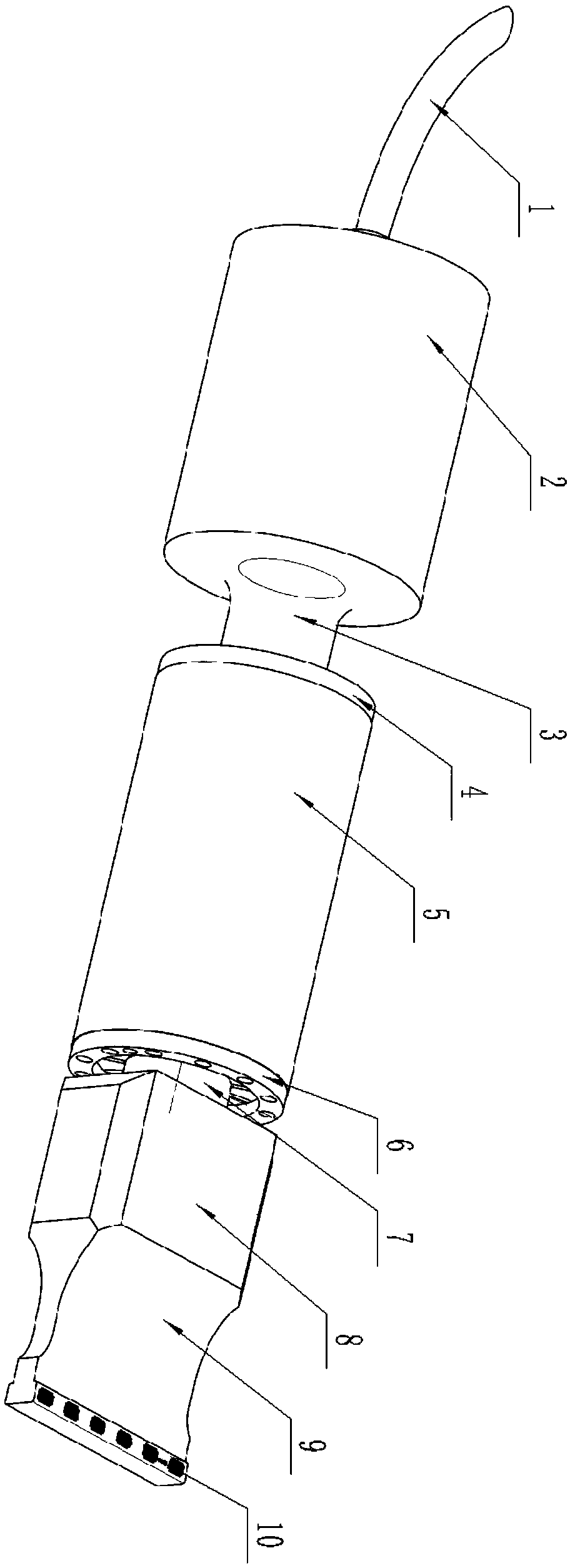
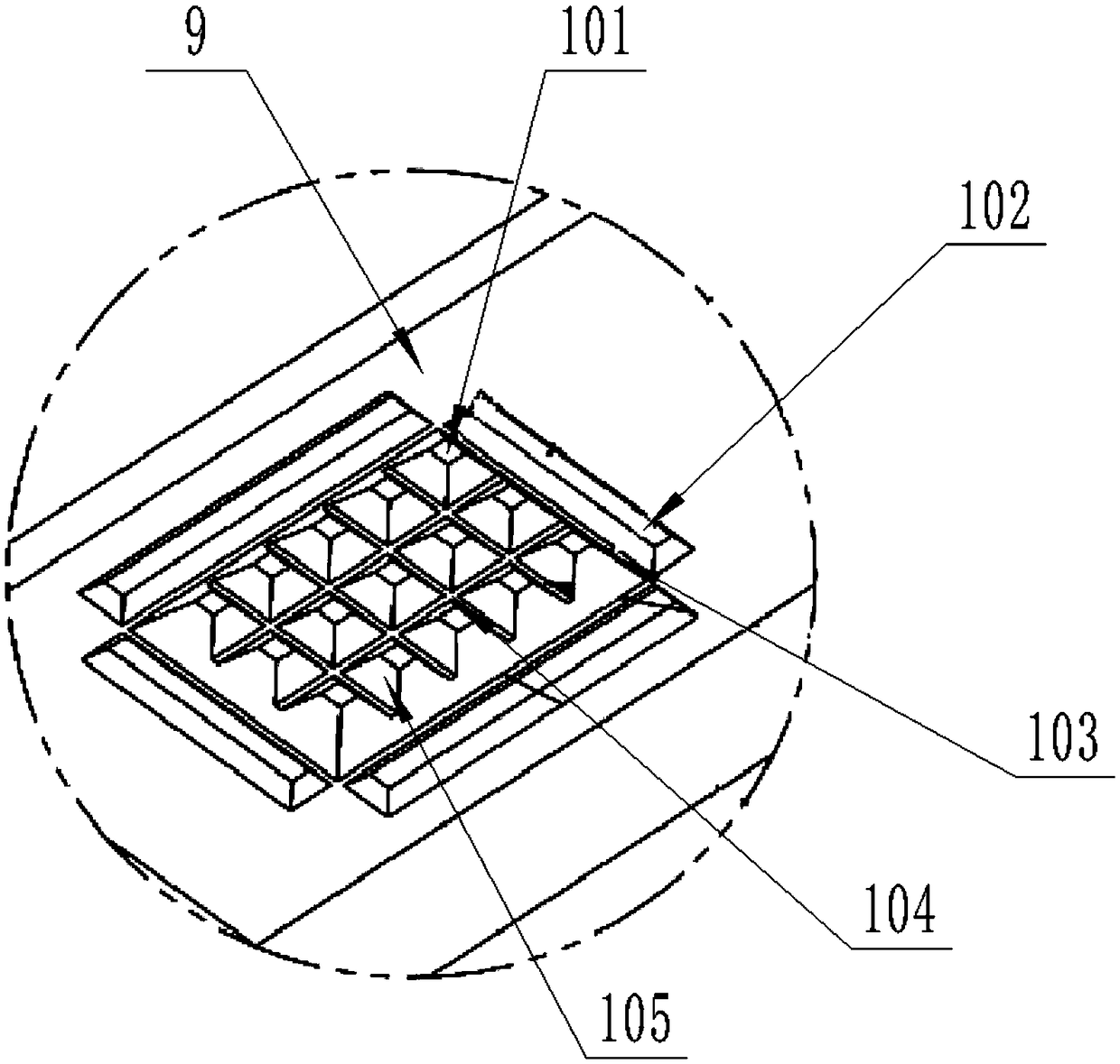
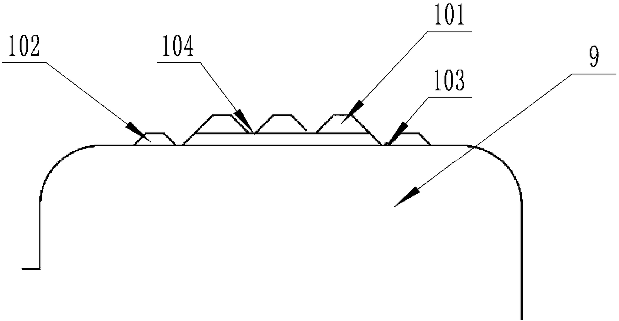
[0014] Such as figure 1 As shown, this specific embodiment adopts the following technical solutions: an ultrasonic welding head, including a signal line 1, a transducer shell 2, a front part of the transducer 3, a rear connecting flange 4, a connecting sleeve 5, a front Connecting flange 6, welding head connection round platform 7, welding head power storage part 8, welding head emitting part 9 and welding head working part 10; the signal line 1 is used to transmit high-frequency and high-voltage electrical signals; the energy conversion The housing 2 of the transducer can be used for clamping and insulation protection to prevent electric shock; the front part of the transducer 3 adopts an inverted funnel shape, which is conducive to the concentration of ultrasonic energy, reduces the influence of transverse waveforms, and improves the efficiency of ultrasonic transmission. Efficiency; the rear connecting flange 4 is mainly used to press the bottom of the transducer, and a cer...


PUM


Abstract

The invention discloses an ultrasonic welding head. The ultrasonic welding head comprises a signal line, a transducer shell, a transducer precursor part, a rear connecting flange, a connecting sleeve,a front connecting flange, a welding head connecting round table, a welding head power storage part, a welding head transmitting part, a welding head working part and the like. Through the special structure design of the end face of a welding head, the problems of slipping, deformation, pseudo soldering and the like occurring in the ultrasonic welding process are solved well, so that the applicability of ultrasonic welding in the metal welding field is further improved and becomes a indispensable link in the lithium cell welding process.

Description

technical field [0001] The invention relates to the field of welding technology, in particular to an ultrasonic welding head. Background technique [0002] In the lithium battery production process, ultrasonic welding has become an irreplaceable technology in battery welding due to its unparalleled advantages such as small welding internal resistance, high efficiency, and low energy consumption. However, because the ultrasonic welding head is limited by its own vibration mechanism in the process of welding different workpieces, it is very easy to cause instability in energy transmission, and then cause slippage, weld breakage, virtual welding, burning and other undesirable phenomena on the welding workpiece. Therefore, how to make good use of ultrasonic welding has become a difficult problem in the industry, and a technology is urgently needed to make up for this deficiency. Contents of the invention [0003] The object of the present invention is to provide an ultrasonic...

Claims


Application Information

Patent Timeline
IPC IPC(8): B23K20/10B23K20/26
CPCB23K20/10B23K20/26
Inventor 周宏建袁承彬石新华段忠福
Owner SBT ULTRASONIC TECH CO LTD
Why Eureka
Try Eureka