Automatic assembly equipment

A technology of automatic assembly and equipment, applied in the direction of metal processing equipment, metal processing, manufacturing tools, etc., can solve the problems of multiple manpower and material resources of axles, and achieve the effect of solving manpower and material resources

Inactive Publication Date: 2019-02-12
SHIJIAZHUANG GREE SMALL HOUSEHOLD ELECTRICAL APPLIANCES +1
View PDF12 Cites 2 Cited by
  • Summary
  • Abstract
  • Description
  • Claims
  • Application Information

AI Technical Summary

Problems solved by technology

[0004] The main purpose of the present invention is to provide an automatic assembly equipment to solve the problem that more manpower and material resources are required for the screening and feeding of the axles in the prior art

Method used


Image

  • Automatic assembly equipment
  • Automatic assembly equipment
  • Automatic assembly equipment

Examples


Embodiment Construction

[0046] It should be noted that, in the case of no conflict, the embodiments in the present application and the features in the embodiments can be combined with each other. The present invention will be described in detail below with reference to the accompanying drawings and examples.

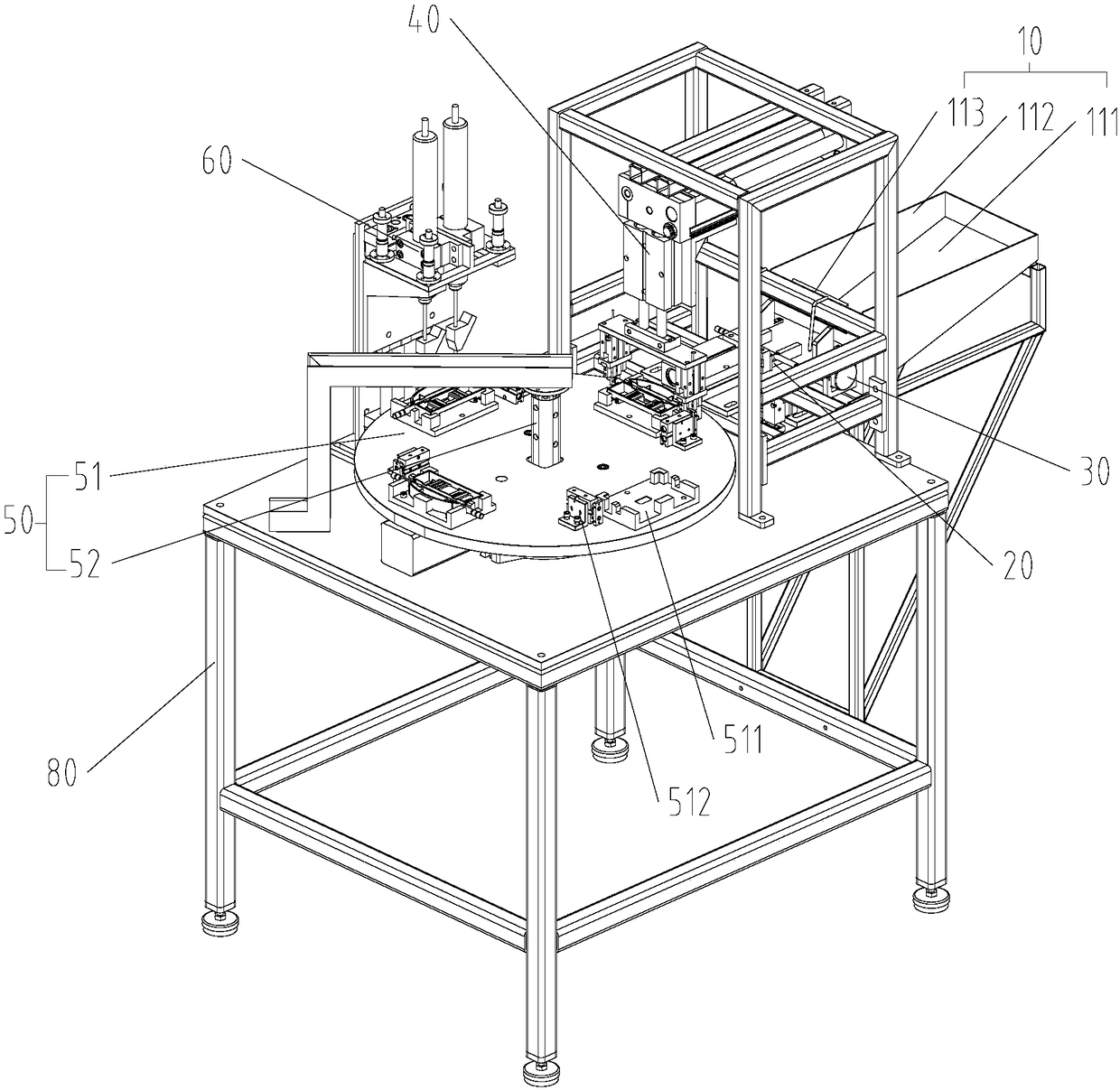
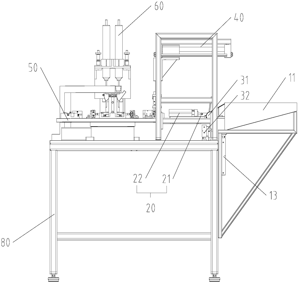
[0047] like Figure 2 to Figure 9 As shown, an automatic assembly device in this embodiment includes a feeding mechanism 10 , and the feeding mechanism 10 includes a hopper 11 , a top sheet 12 and a driving mechanism 13 . The hopper 11 is arranged obliquely, and the bottom of the hopper 11 is provided with a feeding hole. The top material sheet 12 is passed through the top material hole to lift up and transfer the axle 72 . The driving machine 13 is connected with the top material sheet 12 to drive the top material sheet 12 to move.

[0048]Applying the technical solution of this embodiment, the hopper 11 is set to carry the wheel shaft 72, the wheel shaft 72 can be supplied by machine or ma...


PUM


Abstract

The invention provides automatic assembly equipment which comprises a feeding mechanism. The feeding mechanism comprises a hopper, a material jacking piece and a driving machine, wherein the hopper isobliquely arranged, and a material jacking hole is formed in the bottom of the hopper; the material jacking piece penetrates through the material jacking hole to jack up and transfer an axle; and thedriving machine is connected with the material jacking piece to drive the material jacking piece to move. The technical scheme effectively solves the problem that more manpower and material resourcesare needed for the screening and feeding of the axle in the prior art.

Description

technical field [0001] The invention relates to the technical field of automatic assembly, in particular to an automatic assembly equipment. Background technique [0002] The assembly of the electric heating film heating caster frame assembly is carried out manually, the action is single, the degree of automation is low, and the manpower and material resources required are relatively large. The existing semi-automatic equipment can reduce the labor intensity and manpower input, but the caster shaft sieve material supply and the radial circular hole positioning still need to be operated manually, and the requirements for manpower and material resources are still high. [0003] like figure 1 As shown, the caster frame assembly 70 includes a caster frame 71, a wheel shaft 72 and a fixing screw 73, wherein the caster frame 71 is provided with a mounting groove 711, the wheel shaft 72 is installed in the mounting groove 711, and is fixed in the mounting groove 711 by the fixing ...

Claims


Application Information

Patent Timeline
IPC IPC(8): B23P19/00
CPCB23P19/002
Inventor 熊蒙温铭波康纹硕王宏建陈志刚陈丹丹刘锋时海涛刘子鑫康鹏虎安宁李腾飞刘璇李凯周玲冯爱广
Owner SHIJIAZHUANG GREE SMALL HOUSEHOLD ELECTRICAL APPLIANCES
Why Eureka
Try Eureka