
Automatic positioning clamping device and assembly method of steel arch frame

A clamping device and automatic positioning technology, which is applied in the direction of metal processing equipment, metal processing, manufacturing tools, etc., can solve the problems of operator safety hazards and low loop forming efficiency, and achieve the effect of rapid positioning and clamping

Active Publication Date: 2020-08-04
SHANGHAI JIAOTONG UNIV +1
View PDF4 Cites 0 Cited by
  • Summary
  • Abstract
  • Description
  • Claims
  • Application Information

AI Technical Summary

Problems solved by technology

This manual installation method is low in efficiency and poses a great safety hazard to operators

Method used


Image

  • Automatic positioning clamping device and assembly method of steel arch frame
  • Automatic positioning clamping device and assembly method of steel arch frame
  • Automatic positioning clamping device and assembly method of steel arch frame

Examples


Embodiment Construction

[0046] The present invention will be described in detail below in conjunction with specific embodiments. The following examples will help those skilled in the art to further understand the present invention, but do not limit the present invention in any form. It should be noted that those skilled in the art can make several changes and improvements without departing from the concept of the present invention. These all belong to the protection scope of the present invention.

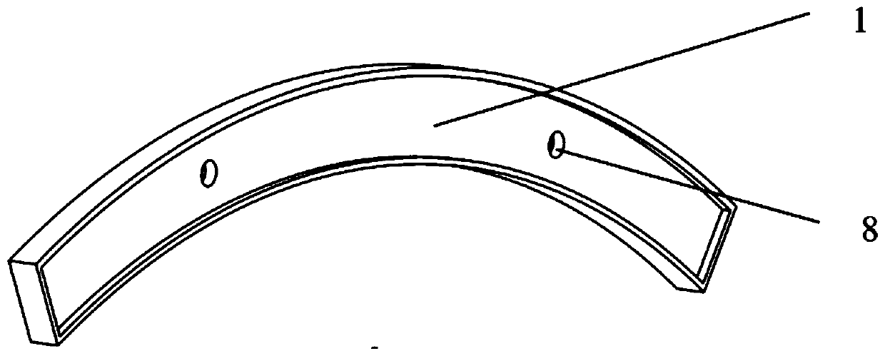
[0047] figure 1 It is a structural schematic diagram of the steel arch 1.

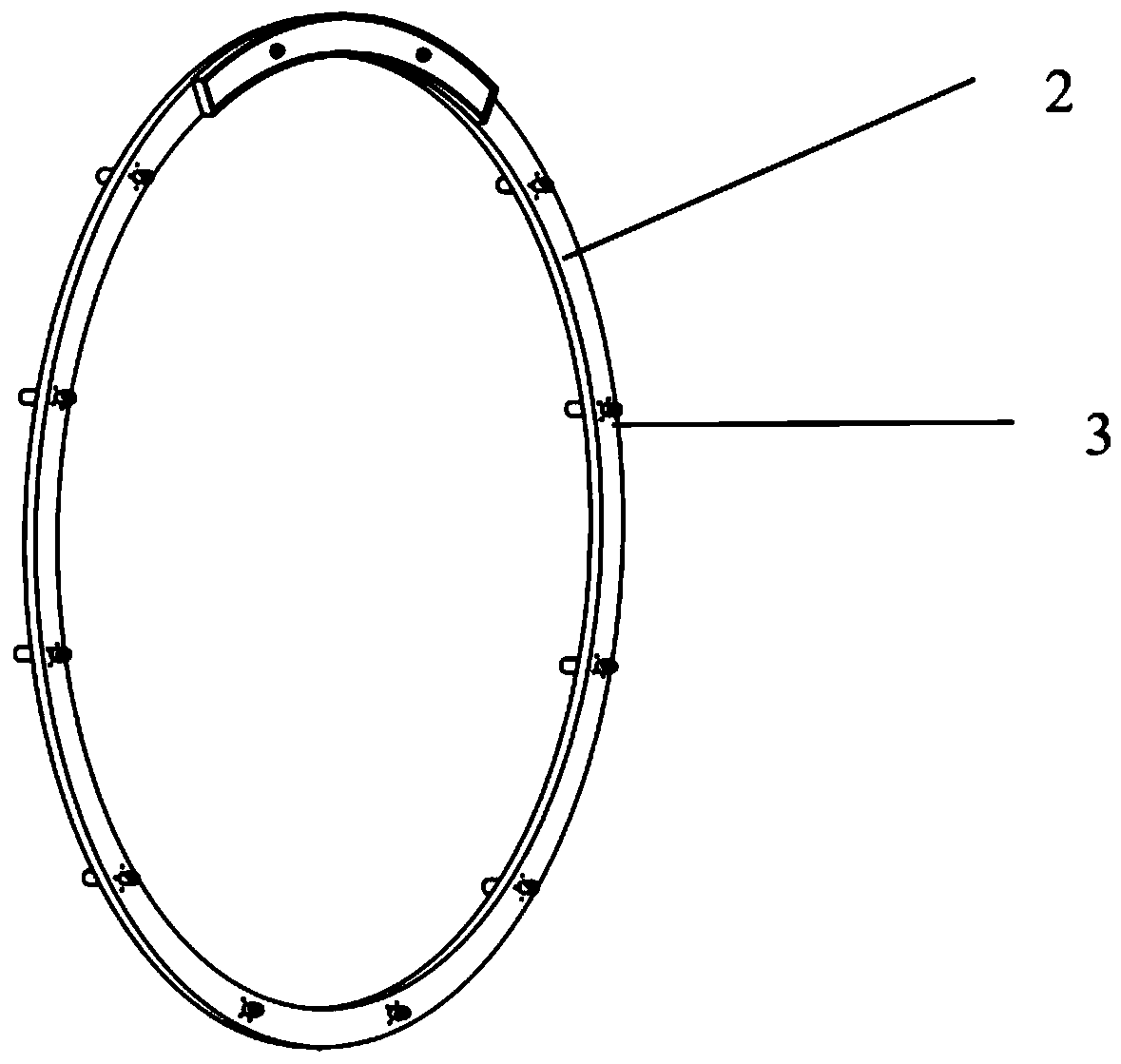
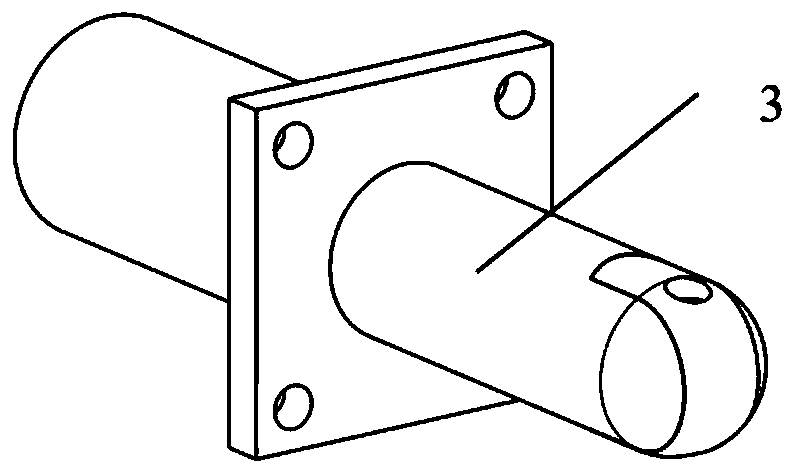
[0048] figure 2 It is a schematic diagram of steel arch assembly. Each steel arch 1 is fixed on the rotating ring 2 through a pair of automatic positioning clamping devices 3, and it goes back and forth until the entire ring is assembled. After the assembly is completed, the automatic positioning clamping device 3 is released, and the tension ring takes out the assembly ring and tightens it.

[0049] The structure and workin...


PUM


Abstract

The invention provides an automatic positioning and clamping device and an assembling method for a steel arch. The automatic positioning and clamping device comprises a sleeve (9), a pushing rod (6) and a sliding block (4); the sliding block (4) is installed on a pushing rod column pin (601) in a sliding manner, and a sliding block column pin (401) located on the side face of the sliding block (4)is assembled in a sliding groove (5) of a groove side face (902) and can slide along the sliding groove (5); and under driving of axial movement of the pushing rod (6) relative to the sleeve (9), thesliding block (4) can move between the unlocking position and the locking position through the guiding effect of the sliding groove (5). According to the automatic positioning and clamping device andthe assembling method for the steel arch, quick positioning and clamping of a steel arch assembling ring can be achieved, the steel arch ring formation efficiency is improved, uncontrollable risks brought by manual installation are reduced, and the important step in TBM full automation is achieved.

Description

technical field [0001] The invention relates to the field of positioning and clamping structures, in particular to an automatic positioning and clamping device. In particular, the invention relates to an automatic positioning and clamping device for a TBM steel arch. Background technique [0002] TBM (Tunnel Boring Machine) refers to the full-section rock tunnel boring machine, which is a special construction machine for hard rock tunnel boring. The functions of excavating and cutting soil, transporting soil muck, assembling tunnel lining, and guiding and correcting deviations by measurement involve many disciplines and technologies such as geology, civil engineering, machinery, mechanics, hydraulic pressure, electricity, control, and measurement, and must be tailored according to different geological conditions. "Type design and manufacture, high reliability requirements. [0003] During the working process of the tunnel boring machine, when the surrounding rock of the tu...

Claims


Application Information

Patent Timeline
Patent Type & Authority Patents(China)
IPC IPC(8): B23P19/00
CPCB23P19/00B23P19/006
Inventor 刘成良刘颖陶建峰覃程锦黄武涛
Owner SHANGHAI JIAOTONG UNIV
Learn More