Inner-hole processing clamp of thin-walled part for numerical control lathe

A technology for CNC lathes and thin-walled parts. It is applied in the direction of manufacturing tools, metal processing equipment, and metal processing machinery parts. It can solve the problem of affecting the surface quality of processed products, the clamping force is not easy to control, and the clamping force is easy to clamp. And other problems, to achieve good roundness, improve product surface roughness, uniform force effect

Pending Publication Date: 2019-02-12
田中金属加工(上海)有限公司
View PDF0 Cites 3 Cited by
  • Summary
  • Abstract
  • Description
  • Claims
  • Application Information

AI Technical Summary

Problems solved by technology

[0002] At present, the inner hole processing of thin-walled parts has always been a major problem in the manufacturing industry. Because the wall is thin, it is not easy to clamp, and the clamping is easy to deform, the clamping force of the product is small, the processing efficiency is low, and the rigidity of the clamping of the parts is poor. , easy to produce vibrations that affect the surface quality of processed products and tool life
At present, boring soft jaws and elastic sleeves are basically used for clamping. The products clamped by soft jaws are easily deformed, and the inner hole becomes a triangle after processing. For parts with small inner hole tolerances, the scrap is extremely high.
Because the product wall is thin and the supporting force is poor, the clamping force is very small, the cutting parameters are very small during processing, and the efficiency is low
In addition, the el

Method used


Image

  • Inner-hole processing clamp of thin-walled part for numerical control lathe
  • Inner-hole processing clamp of thin-walled part for numerical control lathe

Examples


Embodiment 1

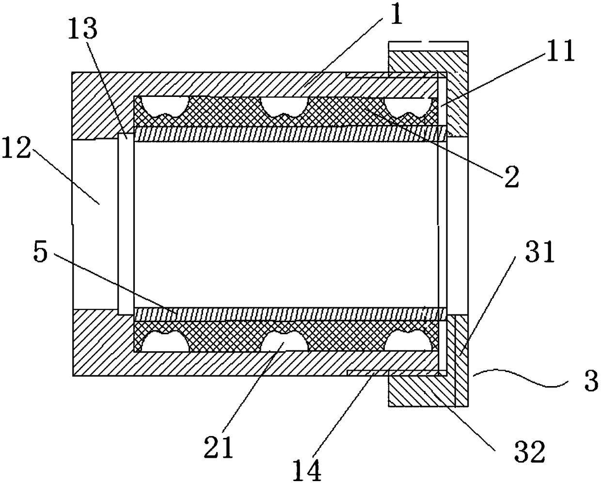
[0022] A jig for machining inner holes of thin-walled parts for CNC lathes, the structure of which is as follows figure 1 As shown, it includes a clamp body 1 sleeved on the outside of the workpiece 5 to be processed and fixed on the CNC lathe, and a clamp cover 3 installed on the front end of the clamp body 1 for clamping the workpiece 5 to be processed. During processing, the workpiece 5 to be processed is inserted into the Located inside the clamp body 1, the clamp cover 3 is fixed on the front end of the clamp body 1, and the clamp cover 3 presses the front end of the workpiece 5 to be processed.

[0023] The center of the clamp body 1 is provided with a columnar channel along the length direction of the clamp body 1. The channel is divided into a front section 11 and a rear section 12. A step 13 is formed between the front section 11 and the rear section 12. The inner diameter of the front section 11 is larger than the outer diameter of the workpiece 5 to be processed. , ...


PUM


Abstract

The invention relates to an inner-hole processing clamp of a thin-walled part for a numerical control lathe. The inner-hole processing clamp comprises a clamp body arranged on the outer side of a workpiece to be processed, in a sleeving manner and fixed on the numerical control lathe and a clamp cover mounted at the front end of the clamp body and used for clamping the workpiece to be processed. During processing, the workpiece to be processed is inserted into the clamp body, and the clamp cover is fixed at the front end of the clamp body and tightly presses the front end of the workpiece to be processed. Compared with the prior art, the inner-hole processing clamp has the advantages that the clamp body is directly clamped by a three-jaw chuck, so that the clamp can be mounted convenientlyand quickly. After mounting of the clamp body, the clamp cover is screwed in to tightly press the workpiece for clamping. The inner-hole processing clamp is suitable for operations of various lengthsand wall thicknesses, and therefore, is strong in applicability. The workpiece to be processed is locked by the clamp cover, so that safe and reliable clamping is realized. The clamp cover is rotatedby a hook spanner for clamping, so that the operation is convenient.

Description

technical field [0001] The invention relates to the field of mechanical processing, in particular to a jig for processing the inner hole of a thin-walled part used in a numerically controlled lathe. Background technique [0002] At present, the inner hole processing of thin-walled parts has always been a major problem in the manufacturing industry. Because the wall is thin, it is not easy to clamp, and the clamping is easy to deform, the clamping force of the product is small, the processing efficiency is low, and the rigidity of the clamping of the parts is poor. , It is easy to generate vibration and affect the surface quality of processed products and tool life. At present, boring soft claws and elastic sleeves are basically used for clamping. The products clamped by soft claws are easily deformed, and the inner hole becomes triangular after processing. For parts with small inner hole tolerances, the scrap is extremely high. Because the product wall is thin and the suppo...

Claims


Application Information

Patent Timeline
IPC IPC(8): B23Q3/12B23Q3/06
CPCB23Q3/06B23Q3/062B23Q3/065B23Q3/12
Inventor 秦国军黄鲁波李天佐
Owner 田中金属加工(上海)有限公司
Why Eureka
Try Eureka