
Automatic mounting mechanical arm for production line

An automatic installation and production line technology, applied in the field of mechanical arms, can solve the problems of easy shaking or sliding, poor quality of glass panel processing, time-consuming and labor-intensive problems, etc., to achieve high degree of automation, expand rotatability, and ensure flexibility.

Active Publication Date: 2019-02-12
重庆智能电控技术有限责任公司
View PDF9 Cites 5 Cited by
  • Summary
  • Abstract
  • Description
  • Claims
  • Application Information

AI Technical Summary

Problems solved by technology

[0005] The purpose of the present invention is to solve the problem that when the existing glass panels are processed, multiple processes are generally required to complete, such as cutting, engraving, loading, etc. After each process is completed, the staff need to go through the production line or manually move The method of transportation transports the glass panel to the next processing workshop for processing. This method not only wastes a lot of time, but also often falls on dust and impurities during the glass transportation process, and the cleanliness of the glass panel is poor. The glass panel is easy to shake or slide when being processed, and the quality of the glass panel processed by the equipment is poor. After the glass panel is loaded after being processed, it needs to be loaded and stored manually, which is very time-consuming and laborious. The degree of automation in the production of the glass panel is very high. low problem, while proposing an automatic installation robot arm for production line

Method used


Image

  • Automatic mounting mechanical arm for production line
  • Automatic mounting mechanical arm for production line
  • Automatic mounting mechanical arm for production line

Examples


Embodiment Construction

[0034] The technical solutions of the present invention will be clearly and completely described below in conjunction with the embodiments. Apparently, the described embodiments are only some of the embodiments of the present invention, not all of them. Based on the embodiments of the present invention, all other embodiments obtained by persons of ordinary skill in the art without creative efforts fall within the protection scope of the present invention.

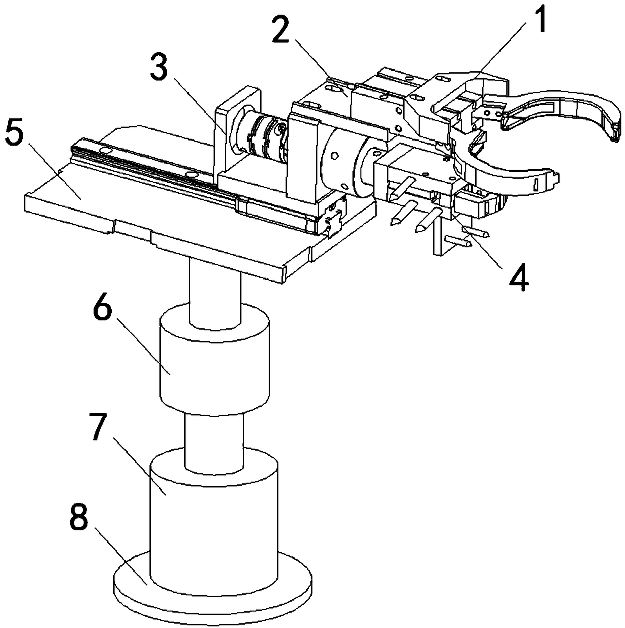
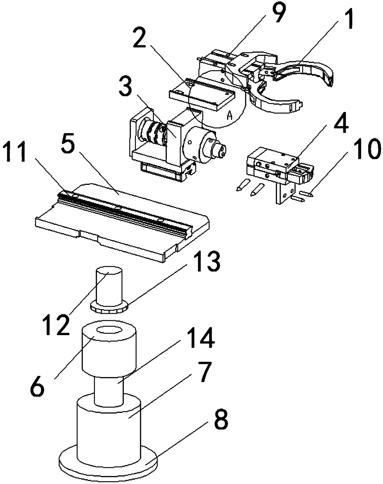
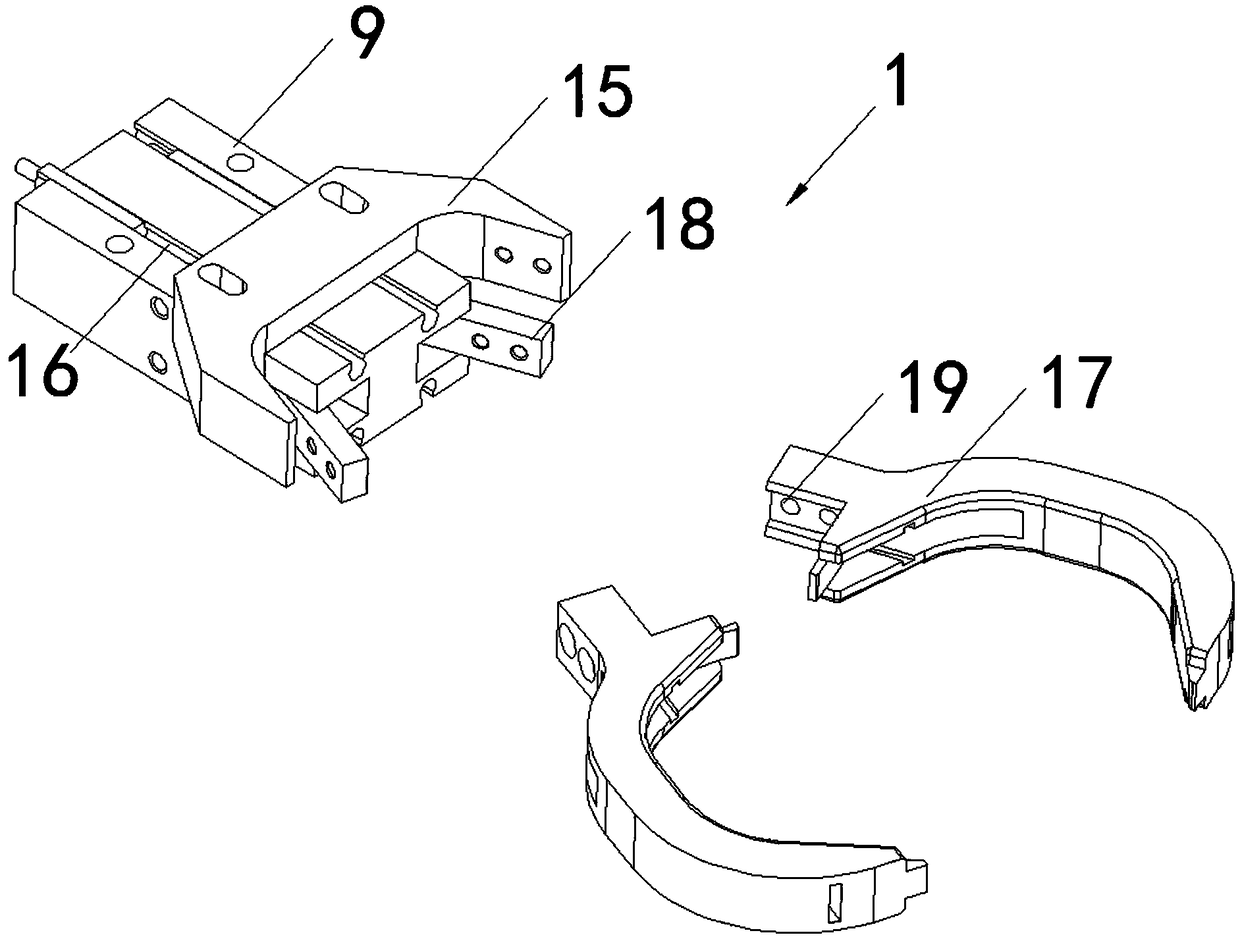
[0035] see Figure 1-9 As shown, an automatic installation mechanical arm for a production line includes an arm claw 1, a transmission frame 3, a mounting seat 4, a pallet 5 and a hydraulic pump 7, a transmission frame 3 is arranged in parallel under the arm claw 1, and the transmission frame 3 A mounting base 4 is installed at one end, and a rectangular support plate 5 is arranged in parallel under the mounting base 4. A PLC controller (manufacturer: Omron) with a model number of CP1H-X40DT-D is installed inside the suppor...


PUM


Abstract

The invention discloses an automatic mounting mechanical arm for a production line. The automatic mounting mechanical arm for the production line comprises an arm paw, a transmission frame, a mountingseat, a supporting plate and a hydraulic pump; the transmission frame is arranged below the arm paw in parallel; the mounting seat is mounted at one end of the transmission frame; the rectangular supporting plate is arranged below the mounting seat in parallel; and a first motor is arranged below the centre of the supporting plate. The automatic mounting mechanical arm for the production line hasthe beneficial effects that the mechanical arm has higher automation degree on production mounting; a third motor drives the mounting seat to rotate through a sleeve shaft so as to quickly adjust thefixing position where a product is screwed by a screw driver on the mounting seat; the hydraulic pump drives the arm paw and the mounting seat to move up and down through a hydraulic post so as to adjust the height of the product grabbed by a paw hook on the arm paw and the height position of the product mounted by the mounting seat; on one hand, higher product mounting efficiency of the mechanical arm is ensured; and on the other hand, the gripping, transporting and mounting of mechanical arm to the products with different sizes and shapes can be ensured, so that the universality of adaptation is ensured.

Description

technical field [0001] The invention relates to a mechanical arm, in particular to an automatic installation mechanical arm used in a production line, and belongs to the technical field of mechanical arm applications. Background technique [0002] With the rapid development of people's living standards, robotic arms are used more and more frequently in mechanical equipment processing production lines. Robotic arms refer to high-precision, high-speed dispensing robots. Robotic arms are multi-input, multi-output, highly nonlinear, strong Coupled complex systems. [0003] In the processing of mechanical equipment production line, the main function of the mechanical arm is to screw and fix the screws between the parts of the mechanical equipment to ensure that when the mechanical equipment is used in the factory, the parts are more firmly connected and not easy to be damaged, which improves the use of mechanical equipment Life, improve the installation efficiency of mechanical ...

Claims


Application Information

Patent Timeline
Patent Type & Authority Applications(China)
IPC IPC(8): B25J18/00B25J18/04B25J15/08
CPCB25J15/08B25J18/00B25J18/04
Inventor 吴和仙郑雅匀徐艳梅
Owner 重庆智能电控技术有限责任公司
Learn More