Optical fiber cutting head zero focus measurement system and method

A technology of measuring system and cutting head, applied in the direction of measuring device, optical instrument testing, testing optical fiber/optical waveguide equipment, etc., can solve the problems of mechanical assembly error, different zero focus position of cutting head, lens error, etc. sexual effect

Active Publication Date: 2019-02-12
HANS LASER TECH IND GRP CO LTD
View PDF4 Cites 2 Cited by
  • Summary
  • Abstract
  • Description
  • Claims
  • Application Information

AI Technical Summary

Problems solved by technology

[0003] In the process of studying the application, the inventor found that there are at least the following problems in the prior art: due to the lens error and mechanical assembly error in the cutting head, the zero focus position of the cutting head is different, in order to ensure different batches of production The cutting head can use the same cutting process parameters when cutting the same plate on the machine tool, so it is necessary to unify the relative height of the zero focus to the end face of the cutting nozzle

Method used


Image

  • Optical fiber cutting head zero focus measurement system and method
  • Optical fiber cutting head zero focus measurement system and method
  • Optical fiber cutting head zero focus measurement system and method

Examples


Embodiment Construction

[0027] In order to facilitate the understanding of the present invention, the present invention will be described more fully below with reference to the associated drawings. Preferred embodiments of the invention are shown in the accompanying drawings. However, the present invention can be embodied in many different forms and is not limited to the embodiments described herein. On the contrary, these embodiments are provided to make the understanding of the disclosure of the present invention more thorough and comprehensive.

[0028] Unless otherwise defined, all technical and scientific terms used herein have the same meaning as commonly understood by one of ordinary skill in the technical field of the invention. The terminology used herein is for the purpose of describing particular embodiments only and is not intended to be limiting of the invention.

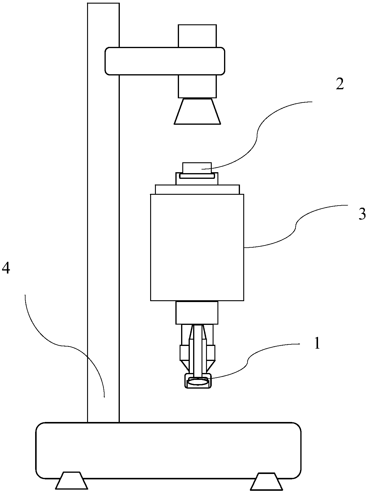
[0029] refer to figure 1 with Figure 4 . The optical fiber cutting head zero-focus measurement system is applied to th...


PUM


Abstract

The embodiment of the invention discloses an optical fiber cutting head zero focus measurement system and method, and relates to the technical field of laser processing. The optical fiber cutting headzero focus measurement system is applied to detecting of an optical fiber cutting head and comprises an optical fiber light-entering point stimulation jig, a cutting nozzle end surface stimulation jig and a lens integrated measuring instrument; the optical fiber light-entering point stimulation jig is mounted at a light-entering opening of the optical fiber cutting head, and the cutting nozzle end surface stimulation jig is mounted at a cutting nozzle of the optical fiber cutting head; and the optical fiber cutting head is arranged on the lens integrated measuring instrument, wherein the lensintegrated measuring instrument emits a first testing light ray and a second testing light ray for measuring of the zero focus absolute height and the cutting nozzle absolute height. According to theoptical fiber cutting head zero focus measurement system, the accuracy of zero focus measurement of the optical fiber cutting head is improved, meanwhile, operation is easy, and batched testing of the optical fiber cutting head can be achieved.

Description

technical field [0001] The embodiments of the present invention relate to the technical field of laser processing, in particular to a zero-focus measurement system and measurement method for an optical fiber cutting head. Background technique [0002] The optical fiber cutting head follower sensor can keep the distance from the cutting nozzle to the surface of the plate floating within the range of 0.8-1mm. At this time, the zero focus of the optical fiber cutting head needs to be unified at 1mm outside the cutting nozzle. [0003] In the process of studying the application, the inventor found that there are at least the following problems in the prior art: due to the lens error and mechanical assembly error in the cutting head, the zero focus position of the cutting head is different, in order to ensure different batches of production The cutting head can use the same cutting process parameters when cutting the same plate on the machine tool, so it is necessary to unify the...

Claims


Application Information

Patent Timeline
Patent Type & Authority Applications(China)
IPC IPC(8): G01M11/00
CPCG01M11/30
Inventor 李典肖俊君陈根余陈焱高云峰
Owner HANS LASER TECH IND GRP CO LTD
Why Eureka
Try Eureka