A fan blade vibration detection device and fault detection and prediction method

A technology for vibration detection and failure prediction, applied in measurement devices, testing of mechanical components, testing of machine/structural components, etc., can solve problems such as inability to analyze and predict

Active Publication Date: 2020-06-30
CHINA TOBACCO ZHEJIANG IND
View PDF7 Cites 0 Cited by
  • Summary
  • Abstract
  • Description
  • Claims
  • Application Information

AI Technical Summary

Problems solved by technology

During the real-time sampling process of fan vibration signals, it will be found that the fan vibration signals are non-linear with each other, and the working process of the fan itself has complex motion characteristics. Different working conditions determine the diversity of judgment results, so it is impossible to analyze and predict. Finding an Applicable Fault Detection and Prediction System

Method used


Image

  • A fan blade vibration detection device and fault detection and prediction method
  • A fan blade vibration detection device and fault detection and prediction method
  • A fan blade vibration detection device and fault detection and prediction method

Examples


Embodiment Construction

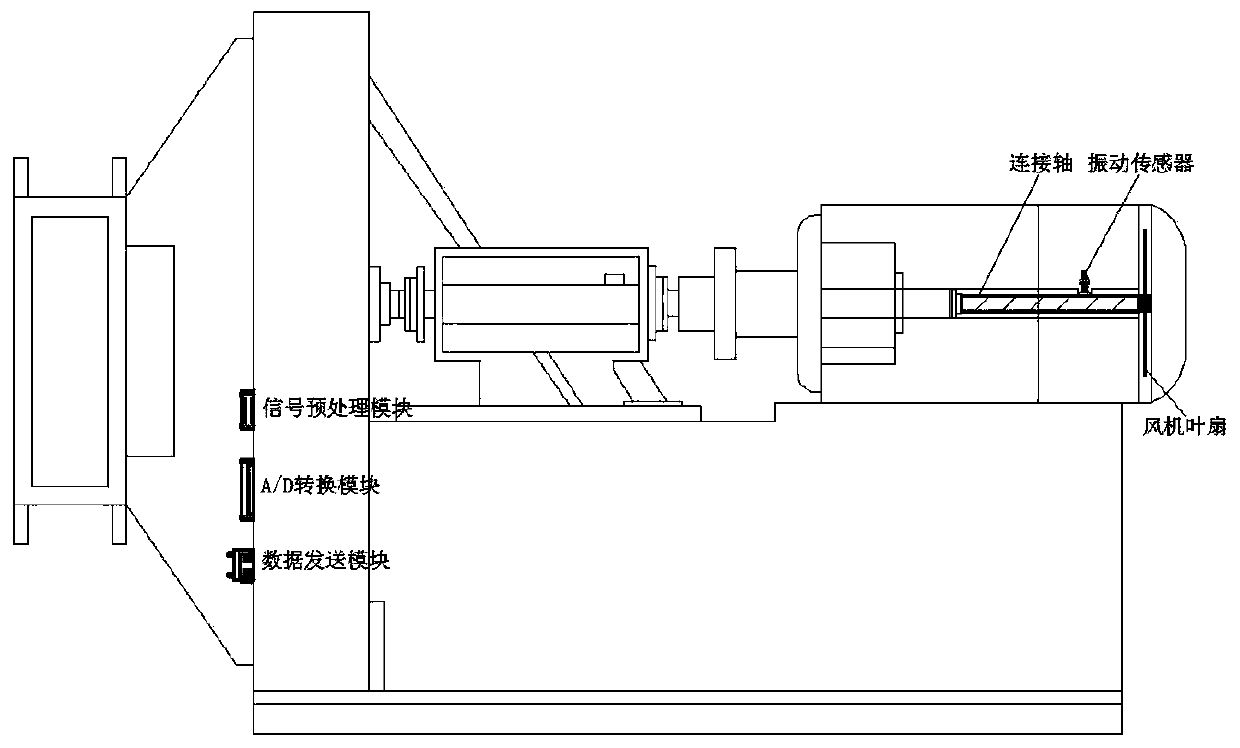
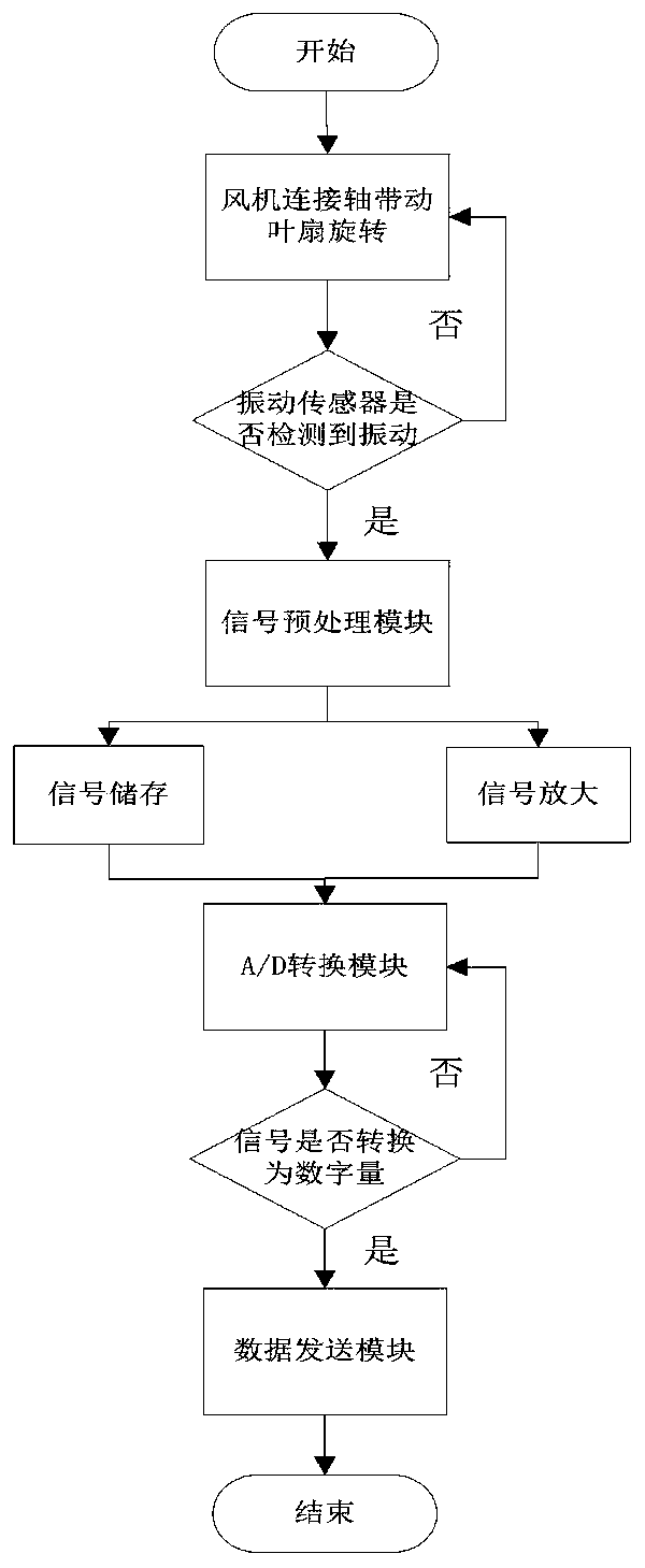
[0063] A fan blade vibration detection and fault prediction system comprises a fan blade vibration detection device and a fan fault prediction method.

[0064] 1.1 A fan blade vibration detection device

[0065] Its structure is as figure 1 As shown, a fan blade vibration detection device includes a vibration sensor, a signal preprocessing module, an A / D conversion module and a data transmission module.

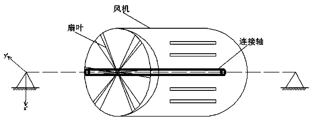
[0066] The vibration sensor is installed on the connecting shaft, and takes the vibration mechanical quantity of the connecting shaft as an input quantity, which is received by its receiving part and converted into electrical pulse output. The vibration generated by the fan during operation mainly comes from the connecting shaft. The connecting shafts with different outer diameters (sz2) and inner diameters (sz1) have different vibration amplitudes during operation for a period of time (t) (that is, dynamic displacement τ) , this vibration amplitude will affect the two crac...


PUM


Abstract

The invention provides a blade vibration detection and fault prediction system for fan. The fan rotates in a circular motion centering on a connecting shaft at a certain rotating speed. The system comprises a fan blade vibration detecting device as a hardware part and a fan fault prediction method as a software part.

Description

technical field [0001] The invention relates to the field of fan mechanical fault diagnosis, in particular to a fan blade vibration detection and fault prediction system. Background technique [0002] The fan is a power device that provides air flow. The fan forms an air flow through the blade fan. The fan blade fan will generate mechanical vibration during the rotation process. If the mechanical vibration is too large, it will cause cracks in the internal connecting shaft and other components until the crack expands and becomes irreversible. The damage of the fan will cause the entire fan to fail or even be scrapped. For this reason, how to carry out preventive detection and judge the crack damage of the mechanical parts in the fan, so as to repair and replace in advance, is the key and difficult problem in the study of the stability of the fan operation. Referring to other similar materials in China, there are many methods proposed for this. For example: Beijing Union Un...

Claims


Application Information

Patent Timeline
Patent Type & Authority Patents(China)
IPC IPC(8): G01M13/00
CPCG01M13/00
Inventor 吕伟何寅岑如春
Owner CHINA TOBACCO ZHEJIANG IND
Why Eureka
Try Eureka