Optical lens

An optical lens and lens technology, applied in the field of optical lens, can solve the problems of poor temperature performance of plastic materials, overall length of the optical system, larger lens volume, etc., and achieve good temperature performance, large field of view, and small FNO effect

Active Publication Date: 2019-02-12
NINGBO SUNNY AUTOMOTIVE OPTECH
View PDF5 Cites 3 Cited by
  • Summary
  • Abstract
  • Description
  • Claims
  • Application Information

AI Technical Summary

Problems solved by technology

When the number of lenses in the optical lens is small (5 to 6), in order to achieve small FNO, small diffuse spots and small distortion, plastic aspheric lenses are usually used to solve the problem, but the temperature performance of plastic materials is poor, which cannot meet- Perfect imaging performance is guaranteed within the temperature range of 40-85°C
Although the glass material has good temperature performance, glass aspheric lens can be used to ensure the temperature performance, but the cost is too high
When the number of lenses in the optical lens is large (≥7~8), in order to achieve a small FNO, the total length of the optical system is usually too long, making the lens volume larger

Method used


Image

  • Optical lens
  • Optical lens
  • Optical lens

Examples


no. 1 example

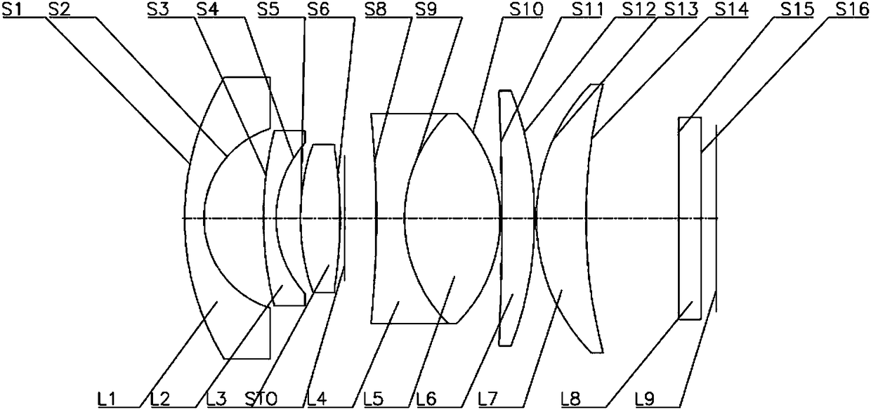
[0117] Such as figure 1 As shown, the optical lens according to the first embodiment of the present invention includes in sequence from the object side to the image side: a meniscus-shaped first lens L1 with negative refractive power, a first surface S1 convex to the object side and a concave first surface S1 A second surface S2 on the image side; a meniscus-shaped second lens L2 with negative power, with a first surface S3 convex to the object side and a second surface S4 concave to the image side; a double lens with positive power A convex third lens L3 with a first surface S5 convex to the object side and a second surface S6 convex to the image side; a stop STO; a double-concave fourth lens L4 with negative power, with a concave The first surface S8 facing the object side and the second surface S9 concave toward the image side; the biconvex fifth lens L5 with positive refractive power has a convex object side that is cemented with the second surface of the fourth lens L4 T...

no. 2 example

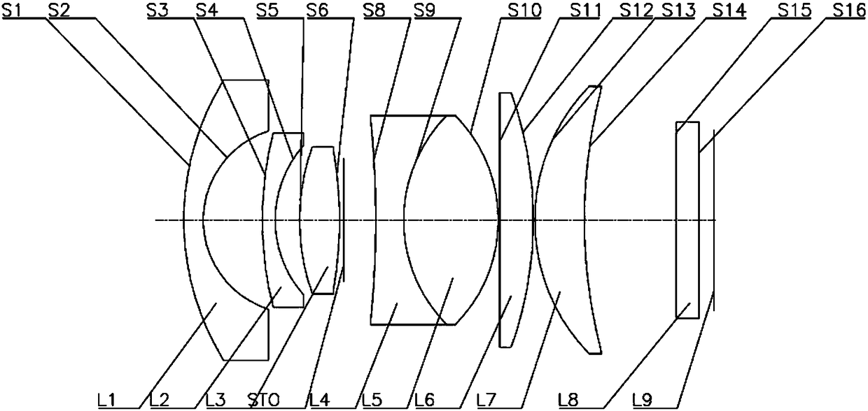
[0127] Such as figure 2 As shown, the optical lens according to the second embodiment of the present invention includes in sequence from the object side to the image side: a meniscus-shaped first lens L1 with negative power, a first surface S1 convex to the object side and a concave first surface S1 A second surface S2 on the image side; a meniscus-shaped second lens L2 with negative power, with a first surface S3 convex to the object side and a second surface S4 concave to the image side; a double lens with positive power A convex third lens L3 with a first surface S5 convex to the object side and a second surface S6 convex to the image side; a stop STO; a double-concave fourth lens L4 with negative power, with a concave The first surface S8 facing the object side and the second surface S9 concave toward the image side; the biconvex fifth lens L5 with positive refractive power has a convex object side that is cemented with the second surface of the fourth lens L4 The first ...

no. 3 example

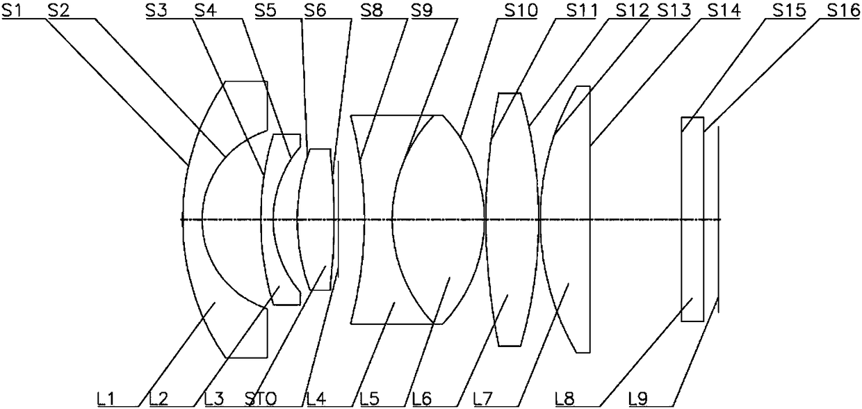
[0137] Such as image 3 As shown, the optical lens according to the third embodiment of the present invention includes in sequence from the object side to the image side: a meniscus-shaped first lens L1 with negative power, a first surface S1 convex to the object side and a concave first surface S1 A second surface S2 on the image side; a meniscus-shaped second lens L2 with negative power, with a first surface S3 convex to the object side and a second surface S4 concave to the image side; a double lens with positive power A convex third lens L3 with a first surface S5 convex to the object side and a second surface S6 convex to the image side; a stop STO; a double-concave fourth lens L4 with negative power, with a concave The first surface S8 facing the object side and the second surface S9 concave toward the image side; the biconvex fifth lens L5 with positive refractive power has a convex object side that is cemented with the second surface of the fourth lens L4 The first su...


PUM


Abstract

The invention provides an optical lens. The optical lens comprises the following in turn from the object side to the image side: a first lens, which is a meniscus lens having negative optical power, wherein the object side surface is a convex surface, and the image side surface is a concave surface; a second lens, which is a meniscus lens having negative optical power, wherein the object side surface is a convex surface, and the image side surface is a concave surface; a third lens, which is a biconvex lens having positive optical power, wherein the object side surface is a convex surface, andthe image side surface is a convex surface; a fourth lens, which is a biconcave lens having negative optical power, wherein the object side surface is a concave surface, and the image side surface isa concave surface; a fifth lens, which is a biconvex lens having positive optical power, wherein the object side surface is a convex surface, and the image side surface is a convex surface; a sixth lens, which is a lens having positive optical power, wherein the image side is a convex surface; and a seventh lens, which is a lens having positive optical power, wherein the object side surface is aconvex surface. According to the optical lens, large field angle, small distortion, small FNO, high relative illumination, and better temperature performance can be realized while keeping the miniaturization of the lens by optimizing the shape of each lens and properly distributing the optical power of each lens.

Description

technical field [0001] The invention relates to the field of optical lenses, in particular to an optical lens capable of realizing a large viewing angle. Background technique [0002] Imaging devices such as camera-mounted mobile devices and digital still cameras using, for example, charge-coupled devices (CCD) and complementary metal-oxide semiconductors (CMOS) as solid-state imaging elements are well known. [0003] In such an imaging device, an optical lens is used to acquire an image of a subject. As more and more electronic devices apply imaging functions, the requirements for optical lenses are also getting higher and higher. For example, the optical lens used in the vehicle field has very high requirements for the small size of the optical lens due to the limitation of the space in the vehicle. At present, in addition to the requirements of high pixel and small size, the conventional vehicle lens has more and more other requirements, such as large field of view, lon...

Claims


Application Information

Patent Timeline
IPC IPC(8): G02B13/06G02B1/00
CPCG02B1/00G02B13/06
Inventor 徐超杨佳张绍鹏
Owner NINGBO SUNNY AUTOMOTIVE OPTECH
Why Eureka
Try Eureka