
Pet food feeding and water feeding device

A technology for water feeders and pets, which is applied in animal feeding devices, animal drinking devices, applications, etc., and can solve the problems of being unable to serve pets, unable to place two kinds of food at the same time, and unable to discharge normally.

Active Publication Date: 2019-02-15
HANGZHOU YUNFENG IND DESIGN CO LTD
View PDF13 Cites 5 Cited by
  • Summary
  • Abstract
  • Description
  • Claims
  • Application Information

AI Technical Summary

Problems solved by technology

[0003] During the use of the above patents, only food can be provided, but drinking water cannot be provided for pets
[0004] In addition, it is impossible to place two kinds of food at the same time to meet the needs of pets, and the above-mentioned patented discharge port is at the lower part of the shell. During the discharge process, due to the extrusion between the feeds, it is easy to cause the phenomenon of material jamming, resulting in the failure of normal discharge. , affecting normal use

Method used


Image

  • Pet food feeding and water feeding device
  • Pet food feeding and water feeding device
  • Pet food feeding and water feeding device

Examples


Embodiment 1

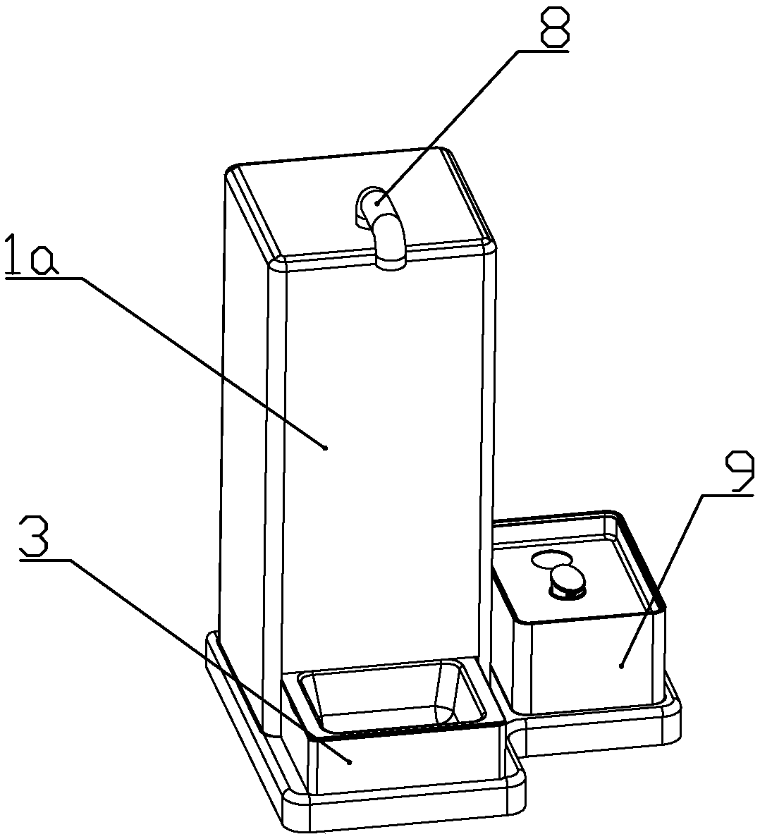
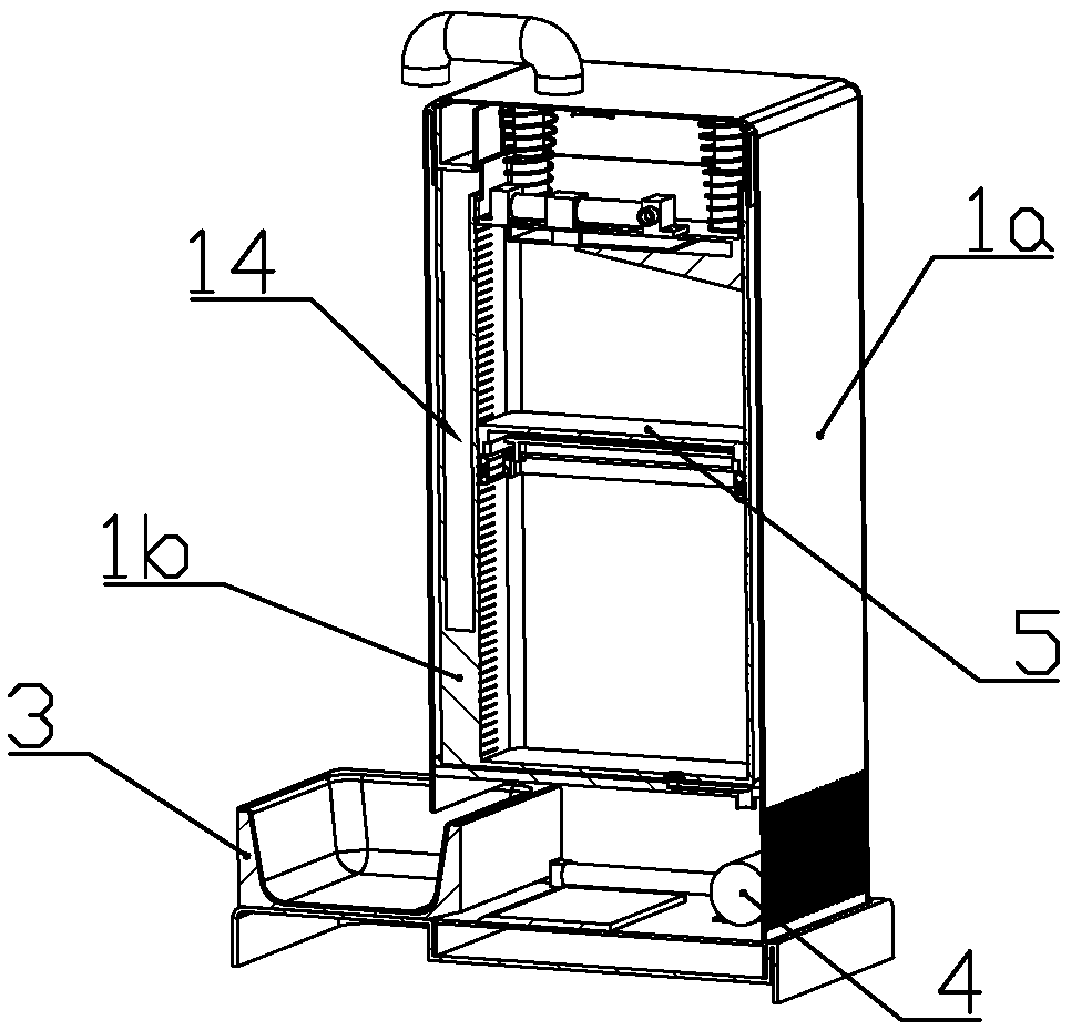
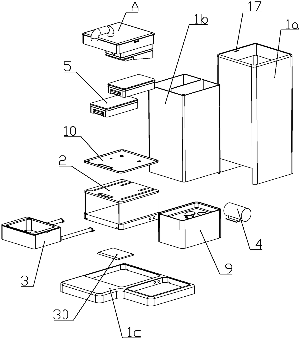
[0079] according to Figure 1 to Figure 24 As shown, a pet water feeder described in this embodiment includes a base 1c, a feeding assembly installed on the upper end of the base, and a drinking assembly 9 installed on the upper end of the base on one side of the feeding assembly. The feeding assembly includes a shell 1a that is detachably connected to the base, a food pan seat 3 that is slidably installed at the inner lower end of the shell, and an inner barrel installed in the shell above the food pan seat 1b; a food plate 34 for feeding is detachably installed on the food plate seat; grooves are formed on the upper ends of both sides of the food plate seat; the user puts his hand in the groove and pulls the food plate upwards to remove the food The plate is removed; by setting a detachable food plate, it is convenient for users to clean.

[0080] The front portion of the inner barrel is formed with a discharge chamber 14 communicating with the food tray; the upper opening ...

Embodiment 2

[0166] In this embodiment, the following improvements are made on the basis of Embodiment 1: the upper part of the inner wall of the storage chamber is formed with a storage chamber suction hole; the side wall of the storage chamber is formed with a connection between the storage cavity suction hole and the air intake pipe of the air pump The suction pipe of the storage chamber; the pipeline between the suction pipe of the storage chamber and the air intake pipe of the air pump is connected with a first solenoid valve; by controlling the operation of the air pump and the first solenoid valve, the gas in the storage chamber passes through the storage chamber. The suction hole of the feed chamber and the suction pipe of the storage chamber enter the air pump and discharge to the outside, extracting the air between the upper piston and the piston, so that the feed can be kept dry and stored for a longer period of time.


PUM

PropertyMeasurementUnit
Angleaaaaaaaaaa

Abstract

The invention discloses a pet food feeding and water feeding device, which comprises a base, a feeding unit and a drinking water unit. The feeding unit comprises a casing, a plate holder, and an innermaterial cylinder. The inner material cylinder is provided with a discharge chamber and a storage chamber, wherein a piston assembly is sealed and connected in the storage chamber in a sliding manner. An air pump is installed at the bottom of the casing, wherein the piston assembly can drive the feed up or down when the air pump inflates or drains an aeration tank. The drinking water assembly comprises a water storage tank connected with the air pump for storing water and a drinking water tank enclosed at the upper end of the water storage tank for feeding water. The drinking water tank is provided with a first one-way valve in a bottom-up single direction and a second one-way valve in a top-down single direction. The pet food feeding and water feeding device is used for storing differentkinds of feed by setting two storage tanks, thereby providing the feed with different tastes or nutrients to pets. The second one-way valve prevents the water in the water storage tank from flowing from the bottom up into the drinking water tank, which causes the dirt in the filter box to overflow upward.

Description

technical field [0001] The invention belongs to the technical field of pet supplies, and in particular relates to a pet water feeder. Background technique [0002] The Chinese patent document whose document number is CN207118458U discloses a pet automatic feeder, which is composed of a host housing, a granary, a grain handling mechanism, a feeding ramp, a main control circuit module, and a grain handling mechanism driving motor. The feeder also includes a feeding trough and a pressure sensing part, the feeding trough is located below the outlet of the feeding channel, the feeding trough is connected with the main body casing through at least three fulcrums, wherein at least two fulcrums form an approximately horizontal Rotating shaft, the third fulcrum is in contact with the pressure sensing part, the pressure sensing part is connected with the main control circuit, the bottom of the feeding trough is higher than the supporting surface at the bottom of the host housing; the ...

Claims


Application Information

Patent Timeline
IPC IPC(8): A01K5/02A01K5/01A01K7/02
CPCA01K5/0114A01K5/02A01K7/02
Inventor 喻文武
Owner HANGZHOU YUNFENG IND DESIGN CO LTD
Learn More