Medicine extraction equipment

A technology for extracting equipment and medicines, which is applied in grain processing, food science, solid solvent extraction, etc., and can solve problems such as inability to extract in large quantities

Active Publication Date: 2019-02-15
衡阳鑫山机械设备制造有限公司
View PDF13 Cites 15 Cited by
  • Summary
  • Abstract
  • Description
  • Claims
  • Application Information

AI Technical Summary

Problems solved by technology

[0002] For example, a drug extraction equipment control system with publication number CN104035407A includes an application layer, a logic layer and a module layer; the application layer includes production line control, database operation, and running state analysis for operators to operate; the logic layer includes data/ Signal protocol, coding/instruction compilation, input/output functions, to support the operation of the application layer to be e

Method used


Image

  • Medicine extraction equipment
  • Medicine extraction equipment
  • Medicine extraction equipment

Examples


specific Embodiment approach 1

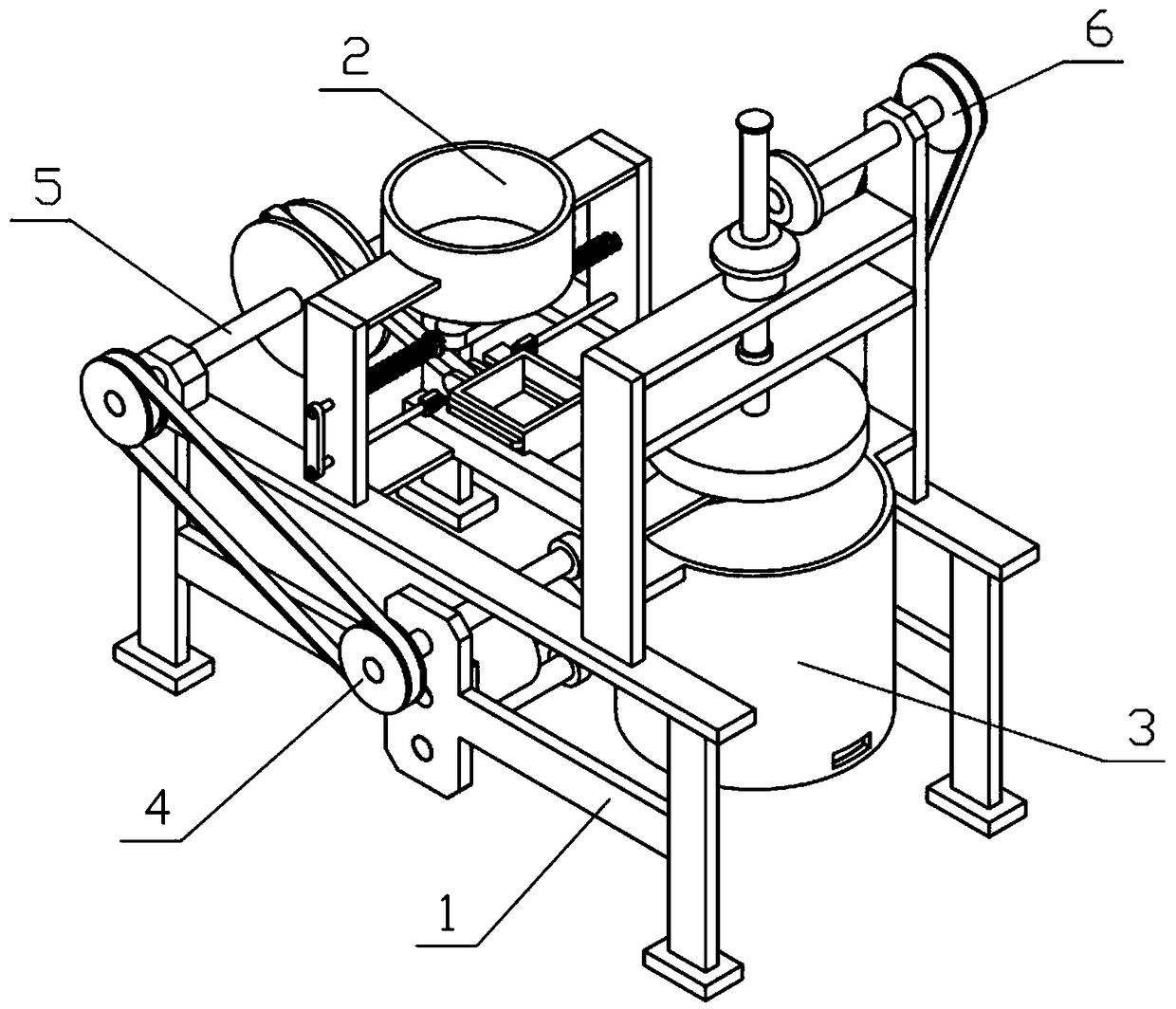
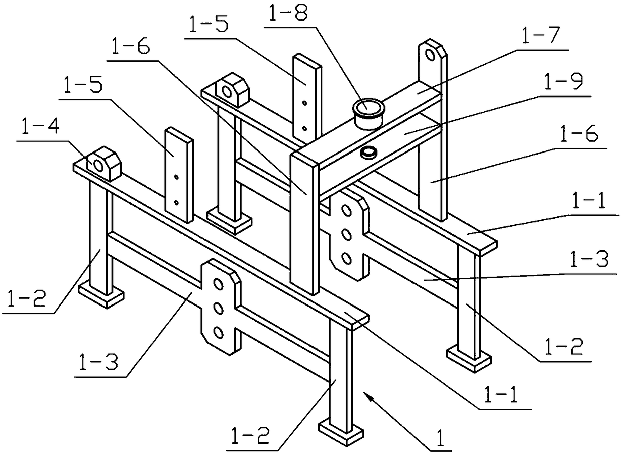
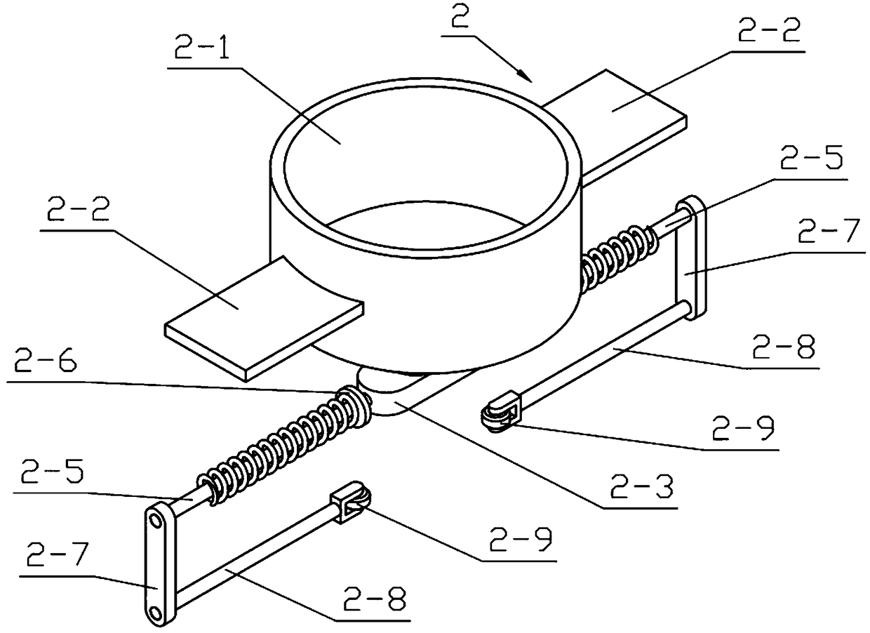
[0031] Combine below Figure 1-10 Describe this embodiment, a kind of drug extraction equipment, including extraction bracket 1, feeding mechanism 2, crushing bracket 3, power mechanism 4, feeding mechanism 5 and crushing mechanism 6, can pass toothless gear 4- 2. The power gear II4-7 and power gear I4-4 realize the intermittent motion of the feeding mechanism 5 and the crushing mechanism 6, and the diameter of the indexing circle of the tooth-missing gear 4-2 is the power gear II4-7 and the power gear I4-4. Twice the diameter of the circle, when the tooth-missing gear 4-2 rotates one revolution, the feeding mechanism 5 and the crushing mechanism 6 work for one cycle. When the feeding mechanism 5 moves, the medicinal materials placed in the discharge barrel 2-1 are transported to the crushing barrel In 3-1, when the crushing mechanism 6 moves, the medicinal materials in the crushing cylinder 3-1 are squeezed and crushed so that the liquid and residue in the medicinal materials...

specific Embodiment approach 2

[0038] Combine below Figure 1-10 Illustrate this embodiment, and this embodiment will further explain Embodiment 1, and described discharge mechanism 2 also comprises push wheel 2-9, and the inner side of two push columns 2-8 is all rotatably connected with push wheel 2-9; Push wheel 2-9 can change sliding friction into rolling friction to reduce the damage caused by friction.

specific Embodiment approach 3

[0039] Combine below Figure 1-10 Describe this embodiment, this embodiment will further explain Embodiment 2, the tooth-missing gear 4-2 is provided with half a ring of teeth, and the index circle diameter of the tooth-missing gear 4-2 is the power gear II 4-7 index Twice the diameter of the circle, the pitch circle diameters of power gear II 4-7 and power gear I 4-4 are equal; when tooth-missing gear 4-2 rotates one circle, it drives power gear II 4-7 and power gear I 4-4 to rotate one circle, When tooth-missing gear 4-2 and power gear II 4-7 mesh transmission, tooth-missing gear 4-2 and power gear I 4-4 withdraw from mesh transmission, and tooth-missing gear 4-2 and power gear II 4-7 withdraw from mesh transmission, tooth-missing gear 4-2 exits mesh transmission. Teeth gear 4-2 and power gear I 4-4 mesh transmission.


PUM


Abstract

The invention relates to extraction equipment, in particular to medicine extraction equipment. The equipment comprises an extraction support, a discharging mechanism, a crushing support, a power mechanism, a feeding mechanism and a crushing mechanism. Intermittent motion of the feeding mechanism and the crushing mechanism can be realized through a tooth-lack gear, a power gear II and a power gearI, the reference diameter of the tooth-lack gear is two times of that of the power gear II and the power gear I, the feeding mechanism and the crushing mechanism moves for one cycle when the tooth-lack gear rotates for one circle, medicines placed in a storage barrel are conveyed into a crushing barrel when the feeding mechanism moves, medicines in the crushing barrel are extruded and crushed whenthe crushing mechanism moves, so that liquids and residues in the medicines are separated, and liquids and residues in the crushed and extruded medicines are separated through a screening plate and afilter plate.

Description

technical field [0001] The invention relates to an extracting device, more specifically to a medicine extracting device. Background technique [0002] For example, a drug extraction equipment control system with publication number CN104035407A includes an application layer, a logic layer and a module layer; the application layer includes production line control, database operation, and running state analysis for operators to operate; the logic layer includes data / Signal protocol, coding / instruction compilation, input / output functions, to support the operation of the application layer to be executed in the device, and the data of the device to be read by the application layer; the module layer includes extracting device control, signal conversion, signal sending and receiving, for Control and provide equipment; the present invention is applied to the integrated control of medicine extraction equipment by an enterprise; the disadvantage of this invention is that it cannot ext...

Claims


Application Information

Patent Timeline
IPC IPC(8): B01D11/02B02C7/08B02C7/14B02C7/16
CPCB01D11/02B02C7/08B02C7/14B02C7/16
Inventor 王璐璐
Owner 衡阳鑫山机械设备制造有限公司
Why Eureka
Try Eureka