Chain wheel sand mould and method for pouring chain wheel by using chain wheel sand mould

A sand mold and sprocket technology, applied in the directions of casting mold, core, casting mold composition, etc., can solve the problems of affecting product size, cumbersome production process, large gas generation of coated sand, etc., so as to improve work efficiency and reduce process. Effect

Pending Publication Date: 2019-02-15
西安合力汽车配件有限公司
View PDF0 Cites 3 Cited by
  • Summary
  • Abstract
  • Description
  • Claims
  • Application Information

AI Technical Summary

Problems solved by technology

[0008] Sand mold clamping refers to the clamping of the upper mold and the lower mold. The gap between the upper mold and the lower mold will form burrs after casting. In severe cases, it will affect the product size and cause the casting to be scrapped. So how to use Better mold clamping of sand molds is a key link in determining the quality of castings
[0009] At the same time, the quality of the casting depends on the molding quality of the coated sand mold. In the traditional technology, the sprocket is generally made by the stacking process. A sand mold has molding cavities on both sides, and every two sand molds form a molding cavity for a casting. Therefore, the sand mold is Solid, thick, large amount of sand, high cost of sand, core coated sand is not easy to be heated and hardened, which affects the strength of the sand mold, uncured coated sand has a large amount of gas, and the casting has many pores and defects, resulting in the overall quality of the sprocket casting The rate is low; while the thickness of the sand mold using the shell molding process is relatively thin, the quality of the sand mold production is good, but only one sprocket casting can be cast at a time, the production efficiency is low, and the labor cost is high
[0010] At present, the traditional technology does not have a sand mold structure with both processes, and the same sand mold is used to superimpose the same sand mold multiple times, resulting in thicker sand molds and a larger sand ratio during pouring. At the same time, the formation of the middle position of the sand mold and The formation of gears requires multiple cores, the structure of the sand mold is complex, and the production process is cumbersome

Method used


Image

  • Chain wheel sand mould and method for pouring chain wheel by using chain wheel sand mould
  • Chain wheel sand mould and method for pouring chain wheel by using chain wheel sand mould
  • Chain wheel sand mould and method for pouring chain wheel by using chain wheel sand mould

Examples


Embodiment 1

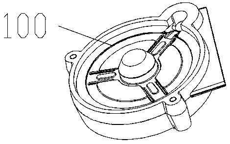
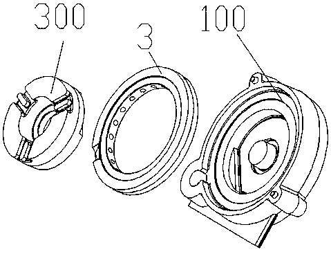
[0055] Refer to attached Figure 5-10 Shown, a kind of sprocket sand mold among the present invention comprises upper shell 1, lower shell 2 and sand core 3, with reference to attached Figure 6-7 As shown, the upper shell 1 is circular, and a first sprue 101 for pouring is provided on one side of the upper shell 1; a first middle hole 102 is provided in the middle of the upper shell 1, and a lower The surface is provided with an annular protrusion 104, and a casting ring 105 is formed between the annular protrusion 104 and the outer edge of the upper shell 1. Several first sprue channels 103 are arranged on the annular protrusion 104, and the first sprue channel 103 and the pouring ring 105 is the same, and the casting ring 105 communicates with the first sprue 101 on the side of the upper shell, and then the pouring liquid can pass through the first sprue 101 and enter the first sprue 103 on the casting ring 105 and the annular protrusion 104; Refer to attached Figure 8-9...

Embodiment 2

[0064] As a further improvement of the above embodiment, in this embodiment, refer to the attached Figure 6-9 As shown, in order to match the truncated conical structure in the middle of the casting, the first pouring cavity 204 is set as a truncated conical cavity with gradually smaller diameter. In the truncated circular cavity, the side with the largest diameter is close to the second middle hole 202 . Furthermore, during pouring, a truncated cone-shaped casting intermediate body can be formed.

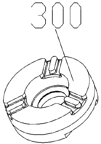
[0065] In this embodiment, in order to ensure the stability of the connection between the sand core 3 and the upper shell 1 and the lower shell 2, in this embodiment, a positioning protrusion 301 is provided on the outer periphery of the sand core 3, specifically, on the sand core 3 At the outer circle of the sand core 3, a circular positioning protrusion 301 can be added, and the circular structure part faces outward, that is, on the outer circle of the sand core 3, there are sev...

Embodiment 3

[0090] In this example, refer to the attached Figure 5-11 As shown, it is necessary to make a WG sprocket. The specific sprocket structure is similar to a handwheel, including an upper and lower ring structure. The inner circle of the ring structure is connected by a connecting ring. There are several convex teeth on the outer periphery of the connecting ring, and a guide frame in the middle. The installation groove, the guide frame installation groove and the annular structure are connected through a connecting body, and the guide frame installation groove includes a hollow cylinder and a boss cavity in the middle.

[0091] In the present embodiment, adopt the sand mold of embodiment 2, prepare sprocket wheel, have steps as follows:

[0092] 1. Place the lower fixture with steel plate first.

[0093] Put down the shell 2 in the fixture, the upper surface of the lower shell 2 faces up, that is, the back faces up (that is, the inner circular straight hole and the guide frame ...


PUM


Abstract

The invention discloses a chain wheel sand mould and a method for pouring a chain wheel by using the chain wheel sand mould. The chain wheel sand mould comprises an upper shell, a lower shell and a sand core, wherein the middle portion of the upper shell is provided with a first middle hole, the upper shell is provided with an annular protrusion, a pouring ring is formed between the annular protrusion and the edge of the upper shell, the annular protrusion is provided with a first pouring channel, and the side of the upper shell is provided with a first sprue communicating with the pouring ring; the middle portion of the lower shell is provided with a second middle hole, the upper and lower surfaces of the second middle hole are provided with a first pouring cavity and a second pouring cavity correspondingly, and the position, corresponding to the first sprue, of the side of the lower shell is provided with a second sprue communicating with the second middle hole; the end of the secondpouring cavity is closed, and the lower shell is provided with a second pouring channel; the sand core is arranged on the annular protrusion in a sleeving manner; and the inner wall of the sand coreis provided with a gear cavity.

Description

technical field [0001] The invention relates to the field of hand wheel manufacturing, in particular to a sprocket sand mold and a sprocket casting method using the sprocket sand mold. Background technique [0002] The casting of metal castings generally uses coated sand molds as molding sand molds, and the sand molds are generally divided into upper and lower shells. The design of the shell needs to take into account the matching relationship between the shells, the flow of the molten metal during casting, that is, the rationality of the design of the runner. [0003] The traditional method of WG sprocket is the laminated sand-coated type, with two lower cores, one outer tooth, and one middle sand core. The amount of sand used is relatively large, and the sand ratio is about 2.8-3.1. The traditional process adopts the overlapping process. Two identical shells are required, and patterns are provided on both sides of the shell. In this case, the thickness of the sand mold is...

Claims


Application Information

Patent Timeline
Patent Type & Authority Applications(China)
IPC IPC(8): B22C9/02B22C9/28
CPCB22C9/02B22C9/28
Inventor 张义涛刘少利叶少腾康健
Owner 西安合力汽车配件有限公司
Why Eureka
Try Eureka