Dense deep hole electric spark hole making method for annular part

A technology of ring parts and EDM, which is applied in the field of dense deep hole EDM drilling of ring parts, can solve the problems of reduced export processing speed, increased labor intensity, and no consideration of mismatching problems, so as to meet production needs and improve processing Effects on Quality and Process Efficiency

Active Publication Date: 2019-02-15
SHENYANG LIMING AERO-ENGINE GROUP CORPORATION
View PDF4 Cites 0 Cited by
  • Summary
  • Abstract
  • Description
  • Claims
  • Application Information

AI Technical Summary

Problems solved by technology

[0003] However, for cooling holes with a diameter of only φ0.7mm to φ1mm, a hole depth of 7mm to 9mm, and a number of more than 10,000 cooling holes, the conventional EDM hole making method has been unable to meet the processing requirements.
[0004] The conventional EDM hole making method is mainly based on setting the inlet flushing liquid, and at the same time, the inlet flushing liquid output by the irrigation method is used to wrap the inlet. The processing stability of the hole exit position is also very easy to cause severe arcing and burn the parts, and it will also reduce the export processing speed
[0005] In addition, in the conventional EDM drilling method, only one set of processing parameters is usually set, and the mismatch between different processing positions and the set of parameters is not considered at all, resulting in poor processing quality and low processing efficiency
[0006] In addition, because the conventional EDM hole making method is mainly used for making holes in annular parts with a small number of cooling holes, the replacement of electrode tubes generally adopts a manual single-piece replacement method, and when the number of cooling holes exceeds 10,000 , it is obviously a waste of time to use manual single-root replacement, and the labor intensity will also increase significantly, which is obviously unable to meet production needs.

Method used


Image

  • Dense deep hole electric spark hole making method for annular part

Examples


Embodiment 1

[0042] In this embodiment, the diameter of the deep hole 8 is 0.7mm, and the depth is 7mm.

[0043] A method for forming dense deep-hole electric discharge holes for annular parts, comprising the following steps:

[0044] Step 1: Preparation Phase

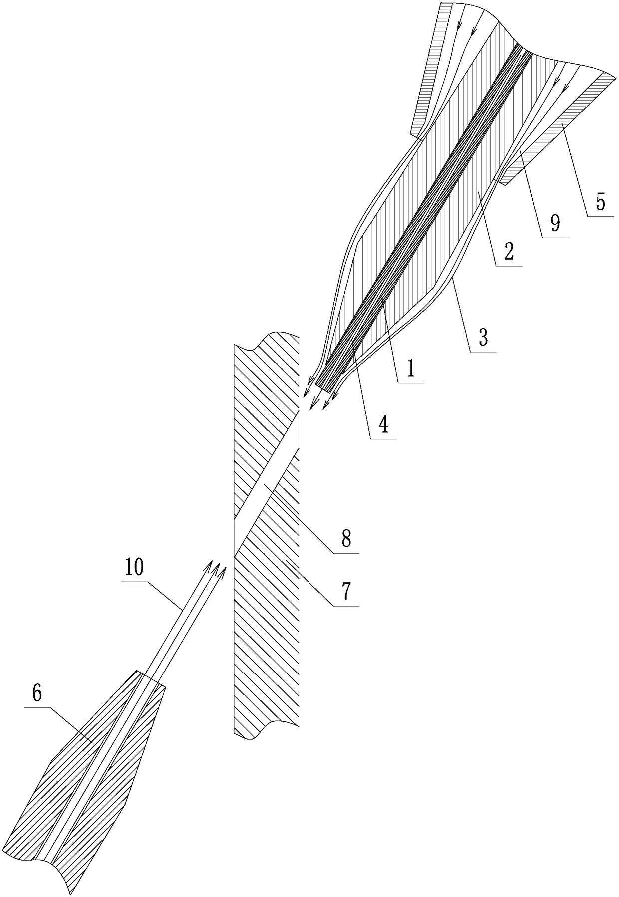
[0045] ①. Transform the electrode catheter 2, and process the end of the electrode catheter 2 into a conical structure;

[0046] ②. Prepare an inlet outer flushing conduit 5, set the inlet outer flushing conduit 5 on the outside of the electrode catheter 2, and form an annular liquid outlet gap 9 between the inlet outer flushing conduit 5 and the electrode catheter 2, and form a ring The liquid outlet gap 9 outputs the inlet flushing liquid 4, and the inlet flushing liquid 4 will flow along the outer surface of the electrode catheter 2 to the surface of the electrode tube 1;

[0047] ③. Prepare an outlet flushing nozzle 6, and connect the outlet flushing nozzle 6 with the bed of the EDM machine through a multi-degree-of-freedom b...

Embodiment 2

[0071] In the present embodiment, the aperture of the deep hole 8 is 0.85mm, and the hole depth is 8mm; the steps of the hole making method refer to embodiment one, and the difference is the processing parameters set in the preparation stage step 6. In the present embodiment, the hole making process The processing parameters of each stage are as follows:

[0072] The processing parameters in the clearing stage are: gap voltage is 60V, servo feed speed is 1mm / min, breakdown voltage is 140V, peak current is 2A, pulse width is 0.5us, and pulse gap is 27us;

[0073] The processing parameters in the rework stage are: the stroke distance is 1.5mm, the gap voltage is 40V, the servo feed speed is 1mm / min, the breakdown voltage is 140V, the peak current is 10A, the pulse width is 10us, and the pulse gap is 8us;

[0074] The processing parameters at the entrance stage are: stroke distance 1.3mm, gap voltage 30V, servo feed speed 1mm / min, breakdown voltage 140V, peak current 13A, pulse w...

Embodiment 3

[0078] In the present embodiment, the diameter of the deep hole 8 is 1 mm, and the depth of the hole is 9 mm; the steps of the hole-making method are with reference to Embodiment 1, and the difference is the processing parameters set in the preparatory stage step 6. In the present embodiment, in the hole-making process The processing parameters of each stage are as follows:

[0079] The processing parameters in the clearing stage are: gap voltage is 60V, servo feed speed is 1mm / min, breakdown voltage is 150V, peak current is 2A, pulse width is 0.5us, and pulse gap is 27us;

[0080] The processing parameters in the rework stage are: the stroke distance is 2mm, the gap voltage is 40V, the servo feed speed is 1mm / min, the breakdown voltage is 150V, the peak current is 10A, the pulse width is 10us, and the pulse gap is 8us;

[0081] The processing parameters at the entrance stage are: stroke distance 1.5mm, gap voltage 30V, servo feed speed 1mm / min, breakdown voltage 150V, peak cu...


PUM


Abstract

The invention relates to a dense deep hole electric spark hole making method for an annular part. The dense deep hole electric spark hole marking method comprises the following steps that firstly, a preparing stage is performed, wherein an electrode conduit is reformed; an external flushing liquid conduit is installed, so that inlet external flushing liquid can flow to the surface of an electrodetube along the outer surface of the electrode conduit; an outlet external flushing liquid nozzle is installed; the annular part is installed; the position of the outlet external flushing liquid nozzleis adjusted so that the spraying direction can be parallel to the central axes of deep holes; and a processing program is compiled, wherein the hole making process in the program is sequentially divided into a zero clearing stage, a repair stage, an inlet stage, a processing stage and an outlet stage, and processing parameters are correspondingly set in each stage; flushing is started; and the processing program is started; and secondly, a hole making stage is performed, wherein processing coordinates are made to return to zero through the zero clearing stage; the shape of the end of the electrode tube reaches the required shape through the repair stage; the shape of the end of the electrode tube is matched with the shape of the processing surface of the annular part through the inlet stage; the hole making of the main parts of the deep holes is completed through the processing stage; and the deep hole outlet processing is completed through the outlet stage. By the adoption of the method, electrode replacement procedures are set based on the principle of high efficiency and time saving.

Description

technical field [0001] The invention belongs to the technical field of electric discharge drilling, in particular to an electric discharge drilling method for dense deep holes of annular parts. Background technique [0002] As an annular part, the aero-engine combustion chamber is densely packed with a large number of cooling holes on its circumferential side wall to reduce the temperature of the combustion chamber. The diameter of these cooling holes is usually φ1mm~φ3mm, and the depth of the cooling holes is The diameter ratio is between 2 and 10, and it is usually made by EDM. [0003] However, for cooling holes with a diameter of only φ0.7mm to φ1mm, a hole depth of 7mm to 9mm, and a number of more than 10,000 cooling holes, the conventional EDM hole making method has been unable to meet the processing requirements. [0004] The conventional EDM hole making method is mainly based on setting the inlet flushing liquid, and at the same time, the inlet flushing liquid outpu...

Claims


Application Information

Patent Timeline
Patent Type & Authority Applications(China)
IPC IPC(8): B23H9/14B23H1/00
CPCB23H1/00B23H9/14
Inventor 张文明杨林青潘珂
Owner SHENYANG LIMING AERO-ENGINE GROUP CORPORATION
Why Eureka
Try Eureka