
Residual stress detection auxiliary device facing non-ferromagnetic part

A residual stress and auxiliary device technology, applied in measuring devices, positioning devices, metal processing machinery parts, etc., can solve the problem that ferromagnetic parts cannot be fixed, and achieve the effect of increasing versatility, easy operation and improving accuracy

Pending Publication Date: 2019-02-15
SICHUAN UNIV
View PDF0 Cites 9 Cited by
  • Summary
  • Abstract
  • Description
  • Claims
  • Application Information

AI Technical Summary

Problems solved by technology

In addition, due to the limited size of the magnetic chuck, it is not possible to fix small ferromagnetic parts

Method used


Image

  • Residual stress detection auxiliary device facing non-ferromagnetic part
  • Residual stress detection auxiliary device facing non-ferromagnetic part
  • Residual stress detection auxiliary device facing non-ferromagnetic part

Examples


Embodiment Construction

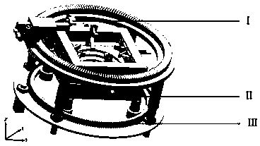
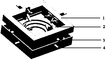
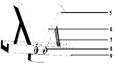
[0023] Such as figure 1 , a structural schematic diagram of an auxiliary device for clamping non-ferromagnetic parts and multi-angle drilling for blind hole method stress detection equipment of the present invention. The feature of the present invention is: comprise the clamping part of non-ferromagnetic parts, its structure is as figure 2 shown; including the multi-angle punching part of non-ferromagnetic parts, its structure is as follows image 3 As shown; the multi-angle punching part includes a coarse adjustment part and a fine adjustment part, and the structure is as follows Figure 4 with Figure 5 shown.

[0024] Such as figure 2 , put the non-ferromagnetic parts between the clamping plates, according to the size of the parts in the Z direction, the movement of the four clamping plates in the Z direction can be adjusted separately by rotating the driving handle to adapt to the clamped parts in the Z direction size. According to the shape characteristics of the ...


PUM


Abstract

The invention relates to a residual stress detection auxiliary device facing a non-ferromagnetic part. The residual stress detection auxiliary device comprises a non-ferromagnetic part clamping mechanism, a non-ferromagnetic part punching rough adjustment mechanism and a non-ferromagnetic part punching fine adjustment mechanism. The non-ferromagnetic part clamping mechanism can regulate the position of a clamping plate according to the size of the minimum cuboid containing body of the part. The non-ferromagnetic part punching rough adjustment mechanism can make a stress-strain piece located within the range of the fine adjustment mechanism. The non-ferromagnetic part punching fine adjustment mechanism can make the plane where the axis of a puncher fixing mechanism is located and the planewhere the punching position on the stress-strain piece is located in the nearly-perpendicular state so that precision of punching can be ensured. By means of the auxiliary device, the method of detecting residual stress through the blind hole method is applied to the aspect of residual stress detection of the non-ferromagnetic part, the accuracy of residual stress detection of the non-ferromagnetic part is improved, universality of a blind hole method residual stress detection device is increased, and operation of the device can be easier.

Description

technical field [0001] The invention relates to the field of blind hole method residual stress detection, in particular to an auxiliary device for clamping non-ferromagnetic parts and multi-angle drilling for blind hole method stress detection equipment. Background technique [0002] With the continuous development of industry, non-ferromagnetic parts such as aluminum alloy and magnesium alloy are more and more used in aerospace, rail, automobile and other fields due to their light weight. The residual stress existing in the non-ferromagnetic parts after processing will make them deform, affect the service life of the parts and even cause the parts to be scrapped. Therefore, it is necessary to detect the residual stress of the non-ferromagnetic parts after processing. The blind hole method is one of the mainstream methods for detecting residual stress at present, and compared with the X-ray method, it can detect the residual stress of parts more accurately. Compared with th...

Claims


Application Information

Patent Timeline
IPC IPC(8): B23Q1/44B23Q3/06B23Q17/00G01L5/00
CPCG01L5/0047B23Q1/44B23Q3/06B23Q17/00Y02P10/20
Inventor 徐雷王峰赵秀粉杨飞平
Owner SICHUAN UNIV
Features
  • Generate Ideas
  • Intellectual Property
  • Life Sciences
  • Materials
  • Tech Scout
  • Unparalleled Data Quality
  • Higher Quality Content
  • 60% Fewer Hallucinations
Learn More