
Wheel sleeve part feeding device

A technology of parts and disc sleeves, which is applied in the field of machining and feeding devices, can solve the problems of difficulty in improving efficiency and long fixture replacement time, and achieve the effect of simple structure, solving the problem of fixture replacement, and improving feeding efficiency

Pending Publication Date: 2019-02-15
YUHUAN CNC MACHINE TOOL
View PDF0 Cites 1 Cited by
  • Summary
  • Abstract
  • Description
  • Claims
  • Application Information

AI Technical Summary

Problems solved by technology

[0002] At present, the feeding method of machined disc sleeve parts is generally manual feeding. The common automatic feeding device can only be used for one type of specification disc sleeve parts, and the parts of different specifications need to be replaced one by one. Difficult to increase efficiency due to long fixture change times

Method used


Image

  • Wheel sleeve part feeding device
  • Wheel sleeve part feeding device
  • Wheel sleeve part feeding device

Examples


Embodiment Construction

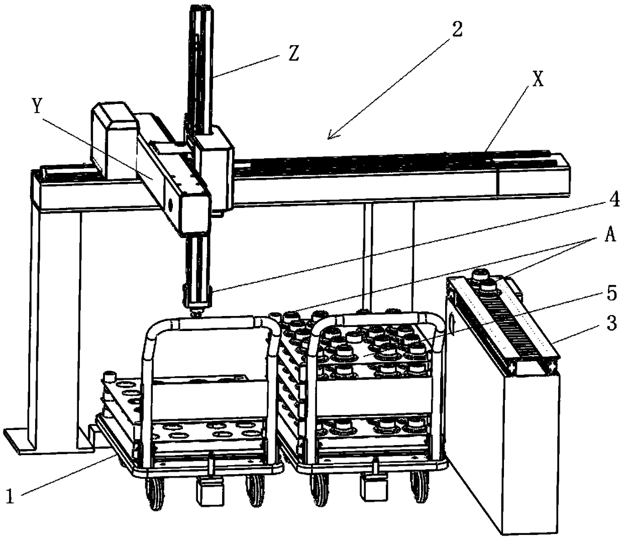
[0027] See figure 1 , the feeding device for disc sleeve parts provided by the present invention comprises a three-axis truss robot 2, two trolleys 1 and their positioning devices, and several pallets 5; the three-axis truss robot 2 consists of Composed of XYZ linear module and pneumatic gripper 4, XYZ linear module includes horizontal axis X, vertical axis Y and vertical axis Z, pneumatic gripper 4 is installed at the lower end of vertical axis Z, and pneumatic gripper 4 is used for grasping part A Picking and releasing, the positioning device of the trolley 1 is set on the ground compatible with the three-axis truss robot 2, and is used to limit the trolley 1 to a designated position to ensure that the three-axis truss robot 2 can grab all parts and Placement tray 5, may also include conveyor belt 3 for transporting parts A.

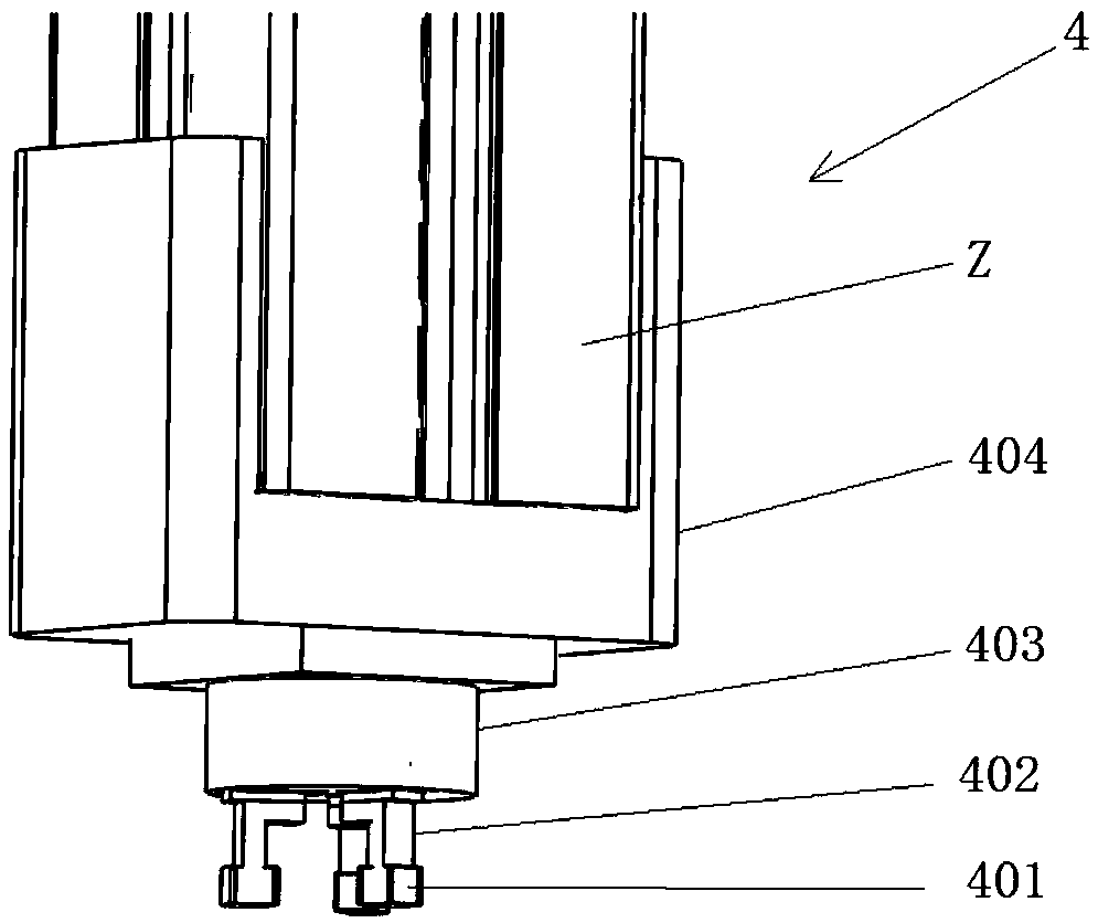
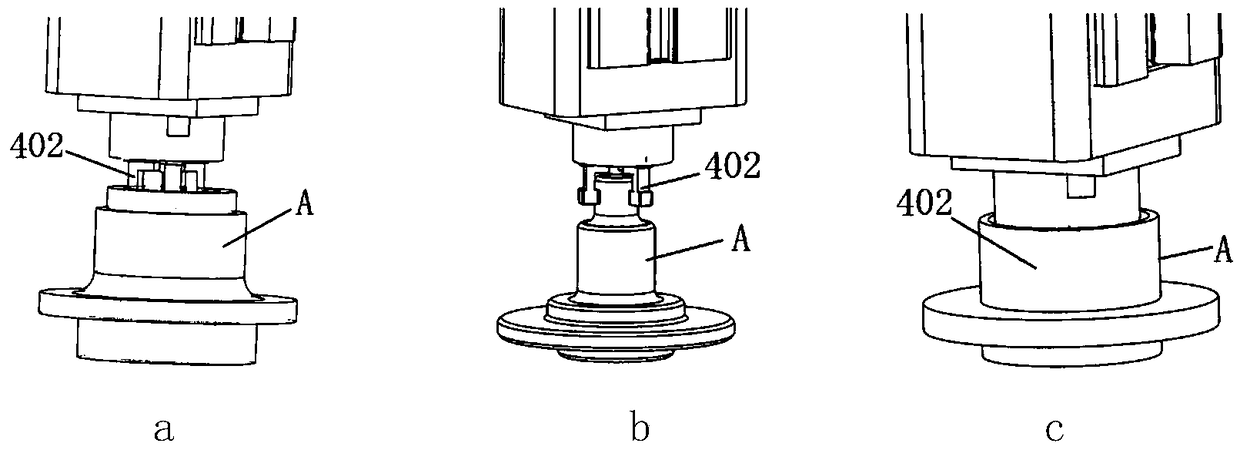
[0028] See figure 2 , the pneumatic gripper 4 consists of a cylinder base 404 installed on the vertical axis Z, a cylinder 403 located on the cylin...


PUM


Abstract

The invention discloses a wheel sleeve part feeding device. The wheel sleeve part feeding device comprises a three-axis truss robot, a hand push trolley, a hand push trolley positioning device and a plurality of pallets. The three-axis truss robot is composed of an XYZ linear module and a pneumatic clamping jaw. The XYZ linear module comprises a horizontal axis X, a longitudinal axis Y and a vertical axis Z. The pneumatic clamping jaw is mounted at the lower end of the vertical axis Z and used for grabbing and releasing parts. The hand push trolley positioning device is arranged on the groundsuitable for the three-axis truss robot and used for limiting the hand push trolley at the designated location to ensure that the three-axis truss robot can grab all the parts and placing the pallets.The wheel sleeve part feeding device has the advantages of good universality and high efficiency.

Description

technical field [0001] The invention belongs to a machining feeding device, and in particular relates to a feeding device for disc sleeve parts. Background technique [0002] At present, the feeding method of machined disc sleeve parts is generally manual feeding. The common automatic feeding device can only be used for one type of specification disc sleeve parts, and the parts of different specifications need to be replaced one by one. It is difficult to improve its efficiency due to the long time for fixture replacement. Contents of the invention [0003] The object of the present invention is to provide a high-efficiency and versatile feeding device for disc sleeve parts. [0004] The technical scheme that realizes the object of the present invention adopts is as follows: [0005] The feeding device for disk sleeve parts provided by the present invention includes a three-axis truss robot, a trolley and its positioning device, and several pallets; the three-axis truss ...

Claims


Application Information

Patent Timeline
IPC IPC(8): B65G47/91
CPCB65G47/91Y02P90/02
Inventor 许亮彭铕华文孝黄骏张欣荣
Owner YUHUAN CNC MACHINE TOOL
Learn More