
hydraulic brake calipers

A hydraulic brake and clamp technology, which is applied in the field of rail vehicle brake systems, can solve problems such as the troublesome replacement of brake pads, and achieve the effects of compact structure, stable installation, and reliable fixation

Active Publication Date: 2021-03-19
NANJING CRRC PUZHEN HAITAI BRAKE EQUIP CO LTD
View PDF5 Cites 0 Cited by
  • Summary
  • Abstract
  • Description
  • Claims
  • Application Information

AI Technical Summary

Problems solved by technology

However, the replacement of the brake pads of the hydraulic brake caliper device used in the braking system of low-floor trams is troublesome, and cannot effectively meet the requirements of domestic light rail low-floor vehicles.

Method used


Image

  • hydraulic brake calipers
  • hydraulic brake calipers
  • hydraulic brake calipers

Examples


Embodiment Construction

[0020] In order to make the purpose, technical solutions and advantages of the embodiments of the present invention more clear, the technical solutions in the embodiments of the present invention will be clearly and completely described below in conjunction with the drawings in the embodiments of the present invention.

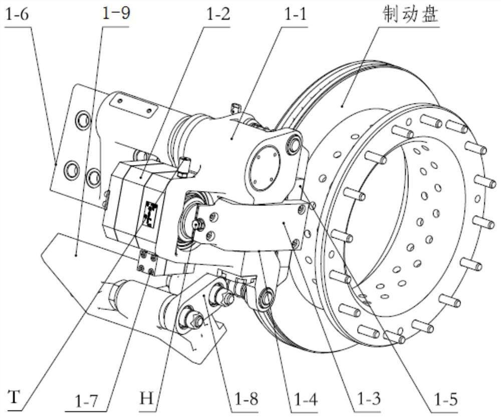
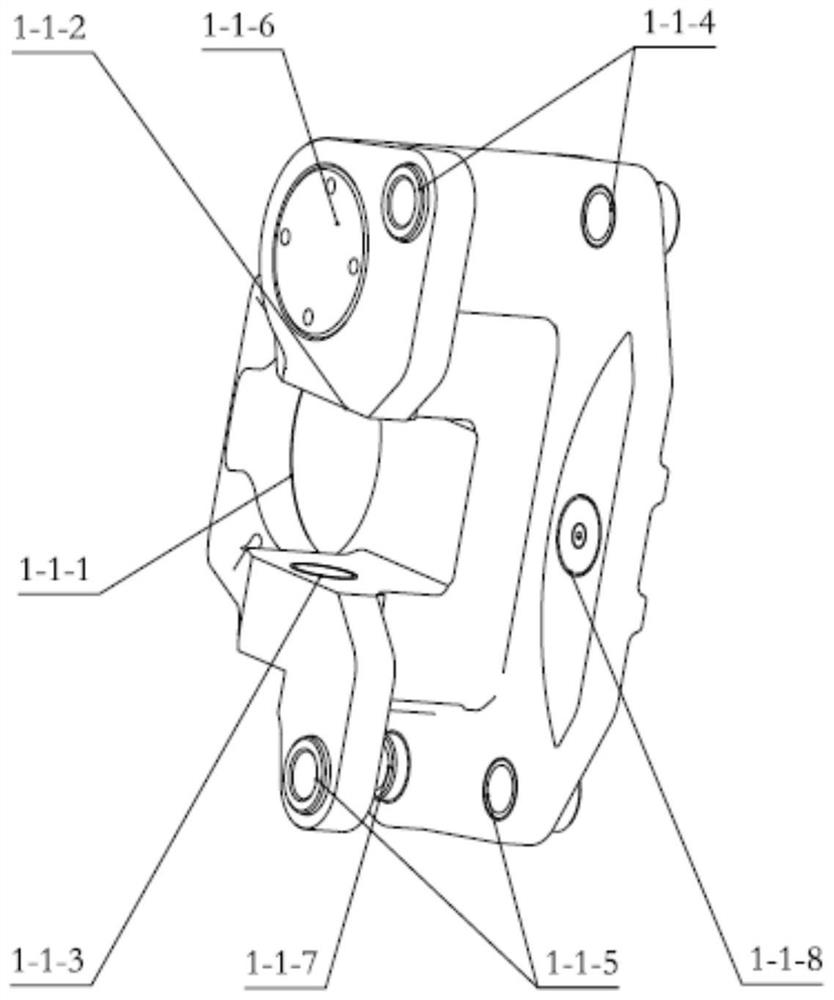
[0021] Such as figure 1 As shown, the hydraulic brake caliper of this embodiment includes a caliper body 1-1, a brake cylinder 1-2 fixed to the caliper body 1-1, and a lever hinged to the caliper body 1-1 through a lever pin 1-4 Assembly 1-3, and the brake assembly 1-5 arranged on the caliper body 1-1, the rear end of the lever assembly 1-3 is suitable for being pushed out by the output head of the brake cylinder 1-2, the lever assembly 1 The front end of -3 is suitable for pressing the brake pad assembly 1-5 towards the direction of the brake disc.

[0022] The pliers body 1-1 is connected to the mounting seat assembly 1-6 through the support pin shaft, the ...


PUM


Abstract

The invention relates to hydraulic brake pincers. The hydraulic brake pincers comprise a pincer body, a brake cylinder fixed to the pincer body, a lever assembly hinged to the pincer body through a lever pin shaft, and a brake lining assembly arranged on the pincer body. The rear end of the lever assembly is suitable for being pushed out by an output head of the brake cylinder. The front end of the lever assembly is suitable for pressing the brake lining assembly to the direction of a brake disc. One end of the pincer body is connected to an installing base assembly through a supporting pin shaft, and the other end of the pincer body is connected to a support assembly through a torque rod assembly. The installing base assembly and the support assembly are suitable for being installed at the shaft end of a vehicle through bolts. The hydraulic brake pincers are compact in structure, convenient to install, easy to maintain and capable of being completed without a special tool, and has hydraulic relieving and mechanical urgency relieving functions. The distance among disc pieces can be adjusted automatically, the adjusting precision is high, and use is safe and reliable. When faults occur, operators can carry out urgent mechanical relieving by rotating a hexagonal resetting screw rod, and normal operation of a vehicle can be guaranteed.

Description

technical field [0001] The invention belongs to the technical field of rail vehicle braking systems, and in particular relates to a floating hydraulic hydraulic braking device. Background technique [0002] For low-floor vehicles, not only the car body structure is different from ordinary trains, but also the braking system is different. The main reason is that the volume of the air source braking system is too large to be installed on the bottom of the vehicle. The hydraulic brake system has the advantages of small size and large torque, so it is applied on low floors. The core component of the basic brake of the hydraulic brake system is the hydraulic brake caliper. [0003] A floating hydraulic brake caliper. When braking, the screw rod of the brake cylinder moves from the inside to the outside under the elastic force of the disc spring in the cylinder to realize the braking process; The hydraulic oil is injected to make the piston and the gap adjustment mechanism comp...

Claims


Application Information

Patent Timeline
Patent Type & Authority Patents(China)
IPC IPC(8): F16D51/24F16D65/56F16D121/04
CPCF16D51/24F16D65/56F16D2121/04
Inventor 余毅权张斌朱新宇汪枫张东升臧传相曹云丽虞晓峰
Owner NANJING CRRC PUZHEN HAITAI BRAKE EQUIP CO LTD
Learn More