Mounting base for industrial robot

A technology for installing bases for industrial robots, which is applied in the direction of engine bases, supporting machines, mechanical equipment, etc., can solve problems such as inability to adapt to robots of various sizes, lack of shock absorbing devices, and shorten the service life of machines, so as to improve the scope of application. Shock absorption effect, noise reduction effect

Pending Publication Date: 2019-02-15
GUANGDONG POLYTECHNIC NORMAL UNIV
View PDF7 Cites 3 Cited by
  • Summary
  • Abstract
  • Description
  • Claims
  • Application Information

AI Technical Summary

Problems solved by technology

[0004] However, the above-mentioned devices lack shock absorbing devices, and long-term operation will reduce the service life of the machine
And the limit groove cannot adapt to robots of various sizes

Method used


Image

  • Mounting base for industrial robot
  • Mounting base for industrial robot
  • Mounting base for industrial robot

Examples


Embodiment 1

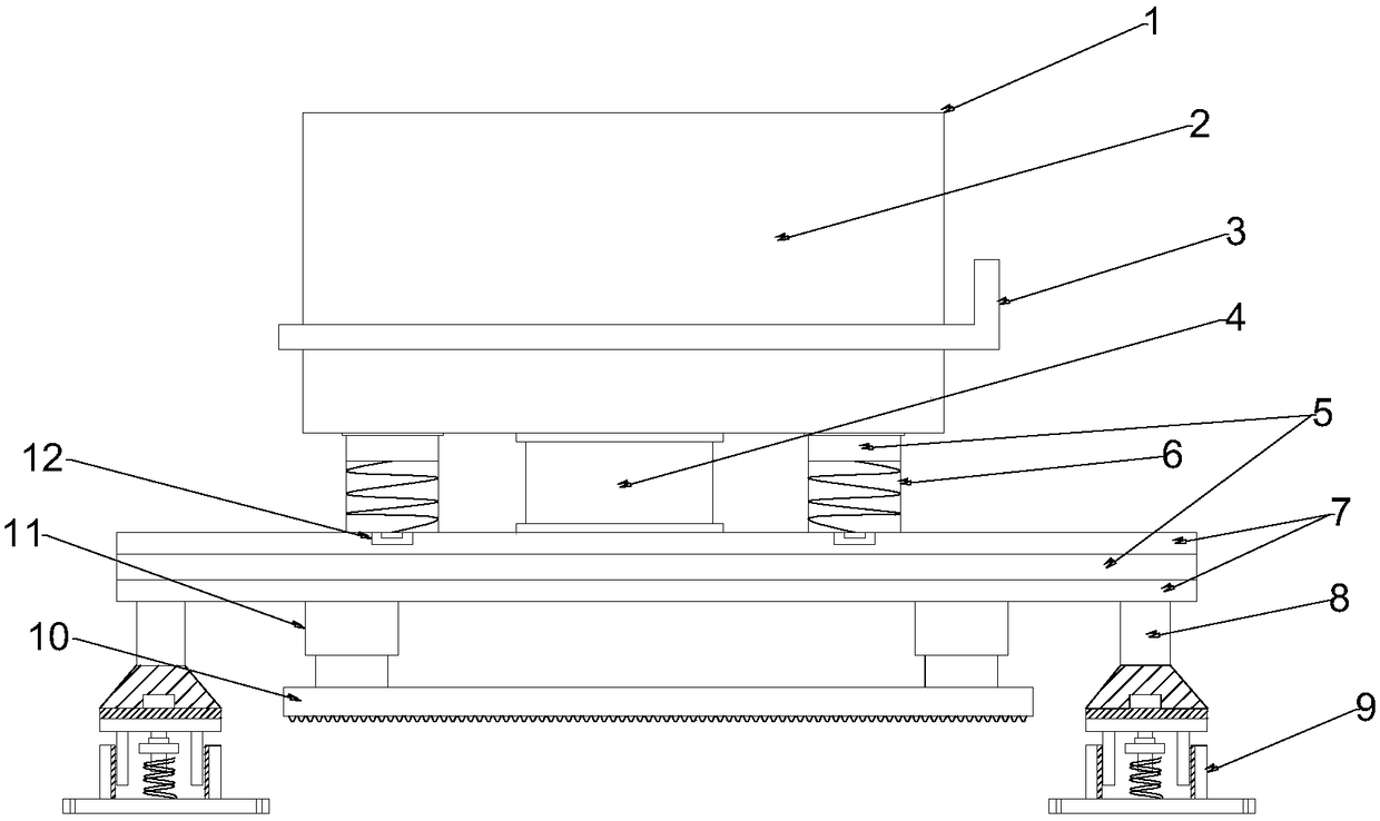
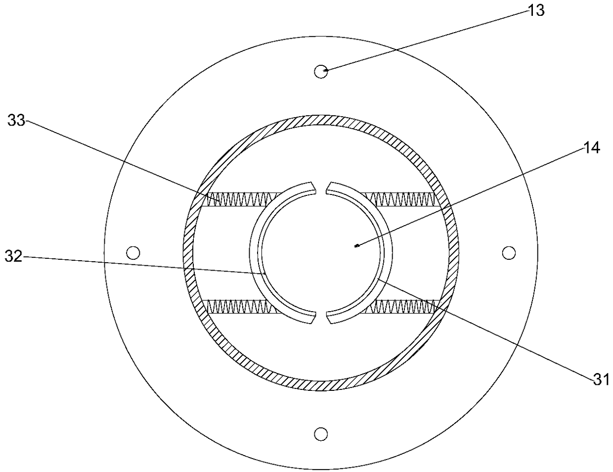
[0021] see Figure 1-2 , in an embodiment of the present invention, a mounting base for an industrial robot includes a robot mounting base 2, the top plate of the robot mounting base 2 is provided with a limiting groove 14 and a fixing bolt hole 13, and the fixing bolt hole 13 is located at the robot mounting base At the four corners of 2, a rotating handle 3 is provided on the outer wall of the robot mounting base 2, the bottom of the robot mounting base 2 is fixedly connected with the rotating shaft 4, and the rotating direction can be rotated by the rotating handle 3, and the two sides of the rotating handle A shock absorber 6 is provided, and the shock absorber 6 is fixedly connected with the robot mounting base 2. The shock absorber 6 can effectively reduce the vibration generated when the robot works. The bottom of the shock absorber 6 is provided with a track 12, and the track 12 The shock absorbing device 6 is rotated together with the robot mounting base 2, and the up...

Embodiment 2

[0025] see figure 1 , in the embodiment of the present invention, on the basis of embodiment 1, a shock-absorbing base 9 is added, and the shock-absorbing base 9 includes a hydraulic controller 20, screws 21, a first rubber pad 22, an upper fixing piece 23, and an inner limit Block 24, limit fixed foot 25, outer limit block 26, second rubber pad 27, first spring 28, buckle 29, nut 30, and the top of described damping base 9 is provided with screw 21, and described screw 21 and The upper fixing piece 23 is connected by bolts, the upper fixing piece 23 is provided with a first rubber pad 22, and the upper fixing piece 23 is provided with an inner limiting block 24, and the inner limiting piece 24 is in contact with the upper fixing piece 23. Welding, the middle of the inner limiting block 24 is provided with a buckle 29, the buckle 29 is detachably connected with the first spring 28 through a nut 30, and the outer side of the inner limiting block 24 is provided with a second rub...


PUM


Abstract

The invention discloses a mounting base for an industrial robot. The mounting base comprises a robot mounting seat and a shock absorption base. A limiting groove and fixed bolt holes are formed in thetop of the robot mounting seat. A rotating handle is arranged on the outer wall of the robot mounting seat. Shock absorption devices are arranged on the two sides of the rotating handle. Rails are arranged at the bottoms of the shock absorption devices. Two fixed plates are arranged at the bottom of the robot mounting seat. A rotating shaft is arranged between each fixed plate and the robot mounting seat. A shock absorption pad is arranged between the two fixed plates. Telescopic rods are arranged at the bottoms of the fixed plates. A reinforcement plate is arranged at the bottoms of the telescopic rods. Telescopic supporting rods are arranged at the four corners of the bottoms of the fixed plates. Shock absorption bases are arranged at the bottoms of the telescopic supporting rods. The mounting base is reasonable in structural design; through the arrangement of the shock absorption bases and the shock absorption pad, the shock absorption effect is enhanced; and through the arrangement of a limiting ring and springs, the application range is widened.

Description

technical field [0001] The invention relates to the technical field of robot equipment, in particular to an installation base for industrial robots. Background technique [0002] An industrial robot is a multi-joint manipulator or a multi-degree-of-freedom machine device for the industrial field. It can perform work automatically and is a machine that realizes various functions by its own power and control capabilities. When installing an industrial robot, it is necessary to use the installation base for fixed support, so that the robot structure is stable and the operation is safer. [0003] Chinese patent (authorized announcement number: CN 206717911U) discloses a mounting base for industrial robots, the top plate of the robot mounting base is provided with a first limit groove and a first fixing bolt hole, the side of the robot mounting base A second limiting groove and a second fixing bolt hole are opened in the plate, and a lateral rotation controller for controlling t...

Claims


Application Information

Patent Timeline
Patent Type & Authority Applications(China)
IPC IPC(8): F16M5/00F16F15/04
CPCF16F15/04F16M5/00
Inventor 王晓军
Owner GUANGDONG POLYTECHNIC NORMAL UNIV
Why Eureka
Try Eureka