Automatic gas filling equipment

A gas filling and equipment technology, applied in the direction of mechanical equipment, equipment loaded into pressure vessels, gas treatment applications, etc., can solve the problems of low efficiency, inconvenient use, increased labor force, etc., to achieve convenient use, improve efficiency, and meet the needs of use effect of demand

Inactive Publication Date: 2019-02-15
开平市富立润滑剂有限公司
View PDF0 Cites 1 Cited by
  • Summary
  • Abstract
  • Description
  • Claims
  • Application Information

AI Technical Summary

Problems solved by technology

Most of the existing filling equipment needs manual picking and placing of bottles, which is inconvenient to use, low in efficiency, and increases labor force

Method used


Image

  • Automatic gas filling equipment
  • Automatic gas filling equipment
  • Automatic gas filling equipment

Examples


Embodiment Construction

[0021] The best embodiment of the present invention will be further described in detail below.

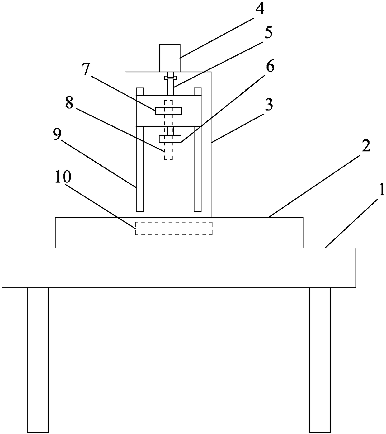
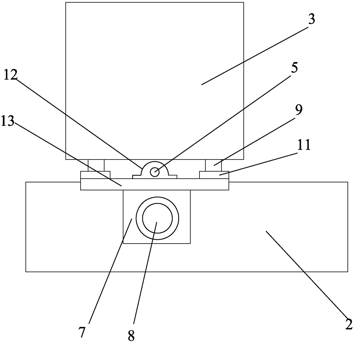
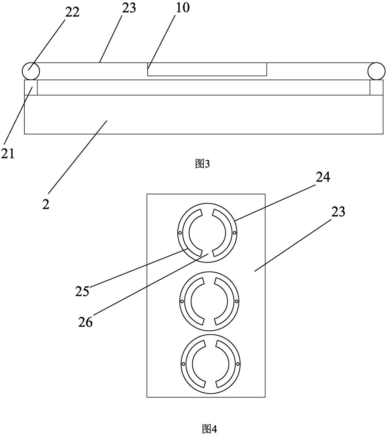
[0022] Such as Figure 1-6 As shown, in the embodiment of the present invention, the automatic gas filling equipment includes a base 1, a conveying device 2, a stand 3, a lifting plate 7, and a filling head 8, and the upper end of the base 1 is fixed with a stand 2, and the stand 2 The front side can be lifted up and down with a lifting plate 7, and a filling head 8 is fixed on the lifting plate 7, and the filling head 8 is connected to the gas to be filled through a pipeline seal; the lower side of the filling head 8 is provided with a fixed The conveying device 2 on the upper end of the base 1, the conveying device 2 mainly includes a conveyor belt 23, the conveyor belt 23 is synchronously connected to the servo motor, the conveyor belt 23 is locked and fixed to the base 24 by screws, the upper end of the fixed base 24 is fixed to a clasp 25, and the clasp 25 is locked Connect t...


PUM


Abstract

The invention discloses automatic gas filling equipment, which comprises a base, a conveying device, a vertical frame, a lifting plate and a filling head. The vertical frame is fixed to the upper endof the base, and the lifting plate is arranged on the front side of the vertical frame in a lifting mode; the filling head is fixed to the lifting plate, and the conveying device fixed to the upper end of the base is arranged on the lower side of the filling head and mainly comprises a conveyor belt; the conveyor belt is connected to a servo motor synchronously, and a fixed base is locked onto theconveyor belt; a clamping ring is fixed to the upper end of the fixed base, and a bottle is clamped in the clamping ring; and an inductor is arranged at the filling head and connected to the servo motor through a circuit, wherein the servo motor is synchronously connected with the conveyor belt. The structural design is simple, using is convenient, gas filling is conducted automatically, manpoweris saved, the cost is lowered, the efficiency is improved, the market using demands are met, and product popularization is facilitated.

Description

technical field [0001] The invention relates to the technical field of cleaning supplies, and in particular relates to an automatic gas filling device. Background technique [0002] Most of the detergents etc. are bottled for high-pressure filling, and then the detergents etc. in the bottle are sprayed out by air pressure. [0003] In the production of cleaning agents, filling is required. Most of the existing filling equipment needs manual picking and placing of bottles, which is inconvenient to use, low in efficiency, and increases labor force. Contents of the invention [0004] The purpose of the present invention is to propose an automatic gas filling device, which overcomes the above-mentioned deficiencies of the prior art. Its structure is simple in design, easy to use, and automatic gas filling is adopted, which saves manpower, reduces costs, improves efficiency, and satisfies the needs of the market. Demand is conducive to product promotion. [0005] In order to...

Claims


Application Information

Patent Timeline
Patent Type & Authority Applications(China)
IPC IPC(8): F17C5/06F17C5/00F17C13/02F17C13/00
CPCF17C5/06F17C5/002F17C13/002F17C13/02F17C2250/03F17C2270/059F17C2270/07
Inventor 何文立
Owner 开平市富立润滑剂有限公司
Why Eureka
Try Eureka