LED module mobile zooming system

A technology of LED modules and zoom systems, applied in lighting devices, cooling/heating devices of lighting devices, light sources, etc., can solve the problems of poor sealing and heat dissipation, achieve weight reduction, increase thermal conductivity, and increase heat dissipation area Effect

Active Publication Date: 2019-02-15
广东博朗灯光音响科技有限公司
View PDF5 Cites 0 Cited by
  • Summary
  • Abstract
  • Description
  • Claims
  • Application Information

AI Technical Summary

Problems solved by technology

[0004] The purpose of the present invention is to provide a mobile zooming system for LED modules in order to increase the effect of moving and zooming LED modules and solve the problems of poor sealing and heat dissipation

Method used


Image

  • LED module mobile zooming system
  • LED module mobile zooming system
  • LED module mobile zooming system

Examples


Embodiment 1

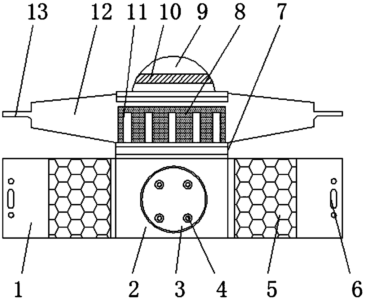
[0024] Example 1, please refer to Figure 1-3 , a mobile zoom system for LED modules, comprising an injection molded housing 1, a circuit board 2 is bonded to the surface of the injection molded housing 1 through double-sided adhesive 5, a power supply base groove 3 is opened in the center of the circuit board 2, and the power supply base groove 3 The central part is embedded with an LED light source 4, and there are four LED light sources 4 in total. The four LED light sources 4 are symmetrically distributed inside the power supply base groove 3, and the illumination intensity can be effectively increased by providing multiple LED light sources 4. Two connecting holes 6 are provided on both sides of the casing 1, and there are two connecting holes 6. The two connecting holes 6 are symmetrically distributed on both sides of the surface of the injection molded casing 1, and the LED module and other accessories can be fixed to each other through the connecting holes 6. connectio...

Embodiment 2

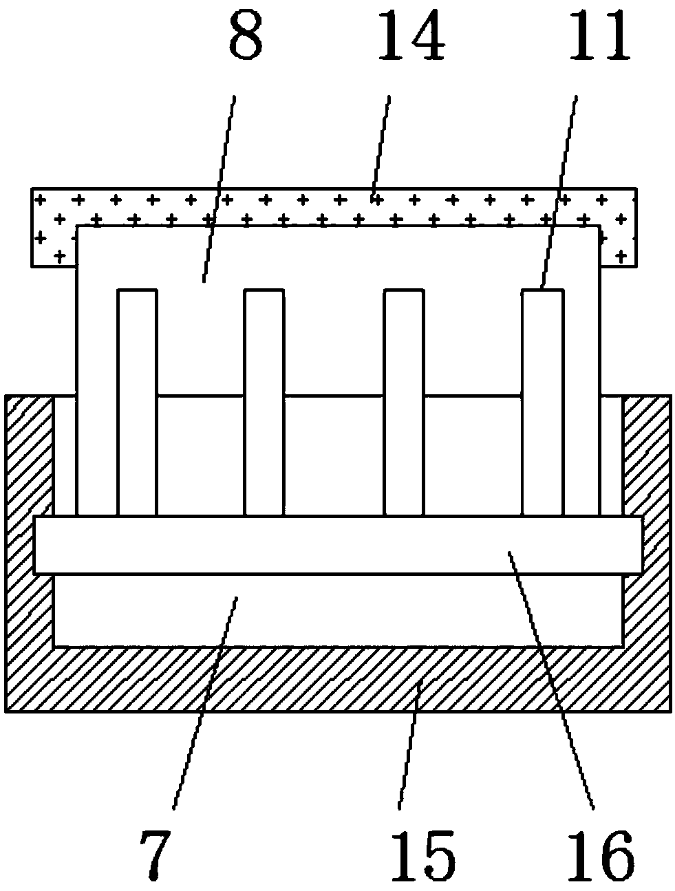
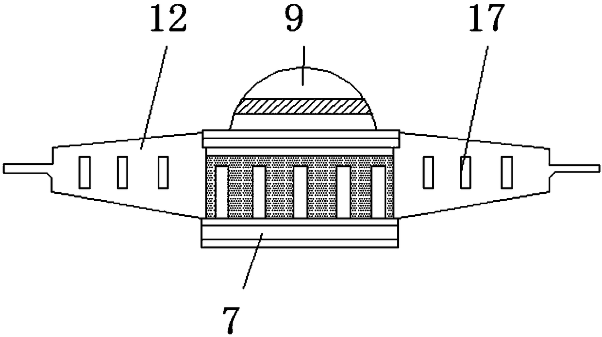
[0025] Example 2, please refer to figure 2 with image 3 There is a chute 15 inside the connecting seat 7, and the inside of the chute 15 is clamped with a substrate 16, and the surface of the substrate 16 is fixedly connected with a guide 11, and the bottom of the telescopic part 8 acts on the surface of the substrate 16, by connecting The seat 7 slides up and down inside the chute 15, and then the telescopic part 8 performs a telescopic movement, and then adjusts the position of the lamp head 9 through the telescopic part 8, and further achieves the effect of zooming. There are multiple guides 11, and multiple guides 11 are distributed on the surface wall of 16 in a circular shape, and a plurality of guide pieces 11 are arranged, and the guide pieces 11 are distributed in a circular shape, which can effectively support and fix the telescopic part 8 .

Embodiment 3

[0026] Example 3, please refer to figure 1 with image 3 , the connecting seat 7 and the telescopic part 8 are cylindrical with both ends open and the interior is a hollow structure, the central axis of the power base groove 3, the connecting seat 7 and the telescopic part 8 is the same straight line, through the structure of the connecting seat 7 and the telescopic part 8, Moreover, the central axes of the power supply base groove 3, the connecting seat 7 and the telescopic part 8 are on the same straight line, which can effectively make the light emitted by the LED light source 4 irradiate the inside of the 9, thereby effectively increasing the light intensity.


PUM


Abstract

The invention discloses an LED module mobile zooming system. The LED module mobile zooming system comprises an injection-molded shell. A power source base groove is bonded to the surface of the injection-molded shell through double-sided adhesive tape. An LED light source is connected to the central portion of the power source base groove in an embedding mode. Two sides of the injection-molded shell are provided with connecting holes. A connecting seat is fixedly connected to the top end of the injection-molded shell. A telescopic part is connected to the interior of the connecting seat in a clamping mode. A threaded cover is rotatably connected to the top of the telescopic part. A lamp cap is rotatably connected to one side of the threaded cover. A lens is arranged in the lamp cap. Heat dissipation plates are fixedly connected to two sides of the telescopic part. Clamping blocks are fixedly connected to one sides of the heat dissipation plates. According to the LED module mobile zooming system, a sliding groove is formed in the connecting seat, a base plate is slidably connected in the sliding groove, and the surface of the base plate is provided with a guide piece, so that the telescopic part can be supported and fixed through the guide piece; and the telescopic part can be moved telescopically through the sliding of the base plate, so that the position of the lamp cap can beadjusted so as to achieve the focusing effect.

Description

technical field [0001] The invention belongs to the technical field of LED modules, in particular to a moving and zooming system of LED modules. Background technique [0002] The LED module is to arrange a certain number of light-emitting diodes together according to the rules and then package them together. The product composed of some waterproof treatment is the LED module. It is mainly used to display advertising fonts (acrylic, blister) and signs at night. Effect, it uses words or logos as the medium, and is installed on the top or wall of the building, which can not only show the daytime effect of the logo, but also use LED as a light source to show another effect at night, and is equipped with LED lighting application control system , Dynamic video control of text or signs, in some places with a strong entertainment atmosphere, LED light source modules have become one of the most important choices for companies to display their self-image. [0003] However, the curren...

Claims


Application Information

Patent Timeline
Patent Type & Authority Applications(China)
IPC IPC(8): F21V14/06F21V29/83F21V29/89F21V31/04F21Y115/10
CPCF21V14/06F21V29/83F21V29/89F21V31/04F21Y2115/10
Inventor 陈巧麦德强
Owner 广东博朗灯光音响科技有限公司
Why Eureka
Try Eureka