Air conditioner and its control method and device

A control method and a technology of a control device, which are applied to control input related to air characteristics, space heating and ventilation control input, space heating and ventilation, etc., can solve problems such as insufficient response and inaccurate control, and achieve comfortable control , control timely and accurately, and ensure the effect of accuracy

Active Publication Date: 2020-10-30
GD MIDEA AIR CONDITIONING EQUIP CO LTD +1
View PDF6 Cites 1 Cited by
  • Summary
  • Abstract
  • Description
  • Claims
  • Application Information

AI Technical Summary

Problems solved by technology

[0004] The embodiment of the present application provides an air conditioner and its control method and device, which solves the inaccurate control and insufficient response in the prior art due to the time lag between the temperature as a single control quantity and the temperature change. problem, by directly using the current capacity output value of the air conditioner and the current room load for predictive control, the control is more timely and accurate, and the technical effect of energy saving and comfort is realized

Method used


Image

  • Air conditioner and its control method and device
  • Air conditioner and its control method and device
  • Air conditioner and its control method and device

Examples


Embodiment 1

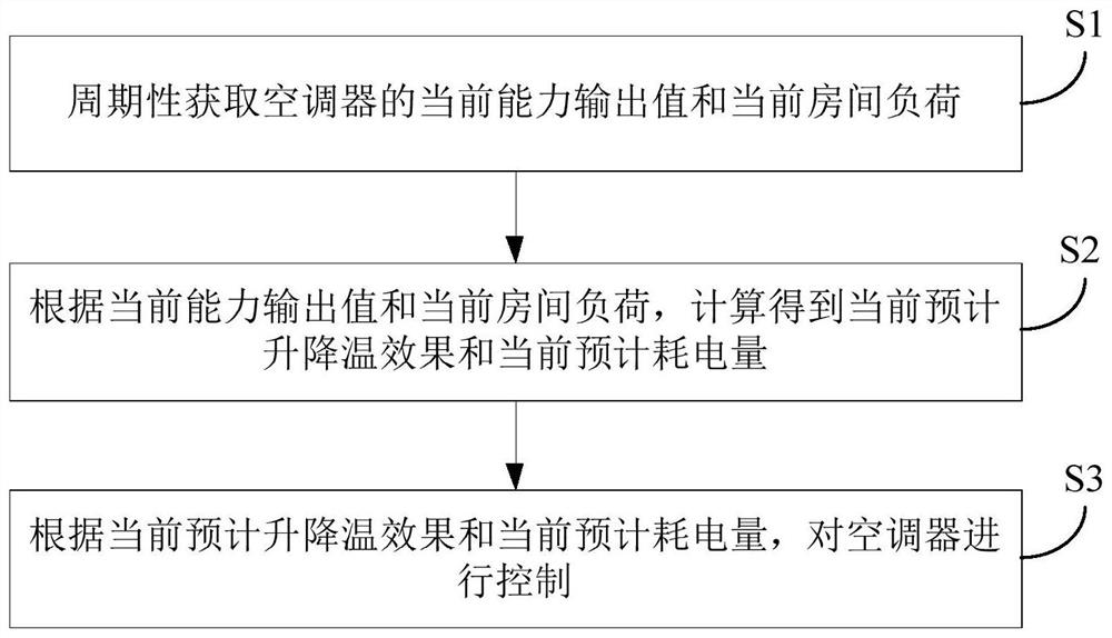
[0030] figure 1 It is a flow chart of the control method of the air conditioner in Embodiment 1 of the present application.

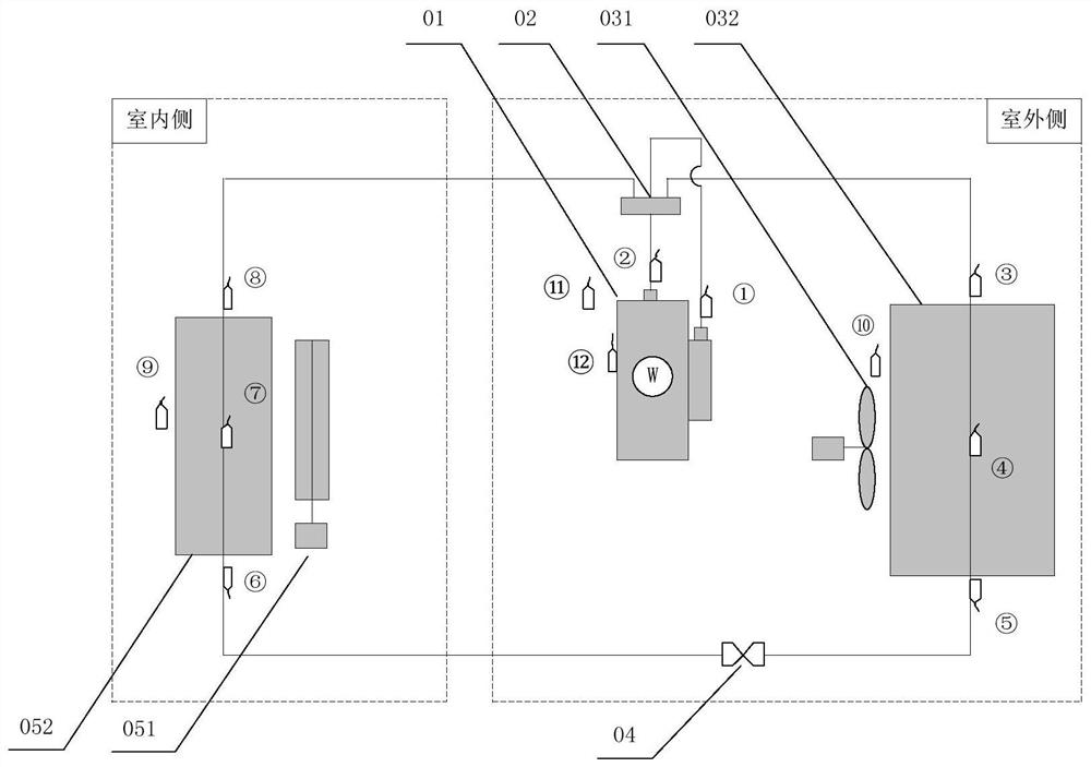
[0031] In the examples of this application, as figure 2 As shown, the air conditioner may include an outdoor side and an indoor side. Wherein, the outdoor side includes a compressor 01 , a four-way valve 02 , an outdoor fan 031 , an outdoor heat exchanger 032 and a throttling component 04 , and the indoor side includes an indoor fan 051 and an indoor heat exchanger 052 . The exhaust port of the compressor 01 is connected to the first end of the four-way valve 02, the second end of the four-way valve 02 is connected to one end of the indoor heat exchanger 052, and the other end of the indoor heat exchanger 052 is connected to the throttle member 04. One end is connected, the other end of the throttling part 04 is connected to one end of the outdoor heat exchanger 032, the other end of the outdoor heat exchanger 032 is connected to the fourth end of th...

Embodiment 2

[0115] Figure 5 It is a schematic block diagram of the control device of the air conditioner in Embodiment 2 of the present application. Such as Figure 5 As shown, the air conditioner control device 100 in the embodiment of the present application includes: an acquisition module 110 , a calculation module 120 and a control module 130 .

[0116] Wherein, the acquisition module 110 is used to periodically acquire the current capacity output value and the current room load of the air conditioner, and the calculation module 120 is used to calculate the current expected heating and cooling effect and the current expected power consumption according to the current capacity output value and the current room load, The control module 130 is used to control the air conditioner according to the current expected heating and cooling effect and the current estimated power consumption.

[0117] According to an embodiment of the present application, the acquisition module 110 is configure...


PUM


Abstract

The invention discloses a control method and device for an air conditioner. The method comprises the following steps that a current capability output value of the air conditioner and a current room load are periodically acquired; the current predicted temperature rising and falling effect and the current predicted power consumption are obtained through calculation according to the current capacityoutput value and the current room load; and the air conditioner is controlled according to the current predicted temperature rising and falling effect and the current predicted power consumption. According to the method, the problem that due to the fact that the time lag exists between the temperature serving as a single control viable and the temperature variation, the control is not accurate and the response is not timely can be effectively solved, the current capacity output value of the air conditioner and the current room load are directly adopted for pre-judgment control, so that the control is more timely and accurate, and then the effects of being energy-saving and comfort are achieved.

Description

technical field [0001] The present application relates to the technical field of air conditioners, in particular to an air conditioner control method, an air conditioner control device and an air conditioner with the control device. Background technique [0002] The existing air conditioner control is mainly based on the PID (Proportion-Integral-Derivative, proportional-integral-derivative) target temperature control method, that is, the user sets the target temperature, humidity, wind speed and other information through the remote control or mobile phone remote control, and the display panel Display the set target temperature and current room temperature, etc. Then, the air conditioner compares the sampled current room temperature with the set target temperature to control the air conditioner to start and run, thereby controlling the entire room temperature to fluctuate around the set target temperature. [0003] However, the inventors of the present application have discov...

Claims


Application Information

Patent Timeline
Patent Type & Authority Patents(China)
IPC IPC(8): F24F11/47F24F11/523F24F11/77F24F11/86F24F11/64F24F110/10F24F110/12F24F110/20F24F110/22F24F140/50F24F140/60
CPCF24F11/47F24F11/523F24F11/64F24F11/77F24F11/86F24F2110/10F24F2110/12F24F2110/20F24F2110/22F24F2140/50F24F2140/60Y02B30/70
Inventor 徐振坤吴楠李金波杜顺开王侃罗羽钊
Owner GD MIDEA AIR CONDITIONING EQUIP CO LTD
Why Eureka
Try Eureka