Detection device and detection method for rebound parameter of concrete

A technology of parameter detection and concrete, applied in the direction of measuring device, testing material hardness, instrument, etc., can solve the problem that the area of ​​the measuring area is difficult to meet the requirements of the specification, the distance should not be less than 20mm, the human error of the measurement result, etc., to improve the measurement accuracy and Accuracy, reducing human error, and the effect of accurate readings

Active Publication Date: 2019-02-15
湖南长建科技有限公司
View PDF15 Cites 4 Cited by
  • Summary
  • Abstract
  • Description
  • Claims
  • Application Information

AI Technical Summary

Problems solved by technology

[0003] In the standard of JGJ / T23-2011 "Technical Regulations for Testing the Compressive Strength of Concrete by Rebound Method", there are many requirements for the measurement area on the surface of the component to be tested. It requires that the measurement points should be evenly distributed in the measurement area. The net distance of the points should not be less than 20mm. When testing the compressive strength of concrete by the rebound method, usually use a ruler, marker pen or chalk to draw the grid lines of the testing area one by one on the components. When the amount of projectile survey area is large, the process of drawing grid lines in the survey area in the traditional way is cumbersome, and the work efficiency of arranging the survey area is low
When the inspector draws the survey area based on experience, the area of ​​the survey area is difficult to meet the specification requirements, which affects the accuracy of the test results
And in the whole process of operating the concrete hammer, you should pay attention to the posture of holding the concrete hammer, hold the middle part of the concrete hammer with one hand, and play the role of righting; hold the tail of the instrument with the other hand, and apply pressure to the instrument. At the same time, it also plays an auxiliary righting role, but it will inevitably make it difficult for the axis of the concrete rebound tester to be always perpendicular to the concrete test surface when operated by hand, which will lead to large human errors in the measurement results.

Method used


Image

  • Detection device and detection method for rebound parameter of concrete
  • Detection device and detection method for rebound parameter of concrete

Examples


Embodiment Construction

[0024] In order to make it easy to understand the technical means, creative features, objectives and effects achieved by the present invention, the present invention will be further explained below in conjunction with specific drawings.

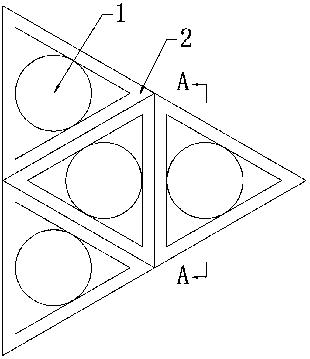
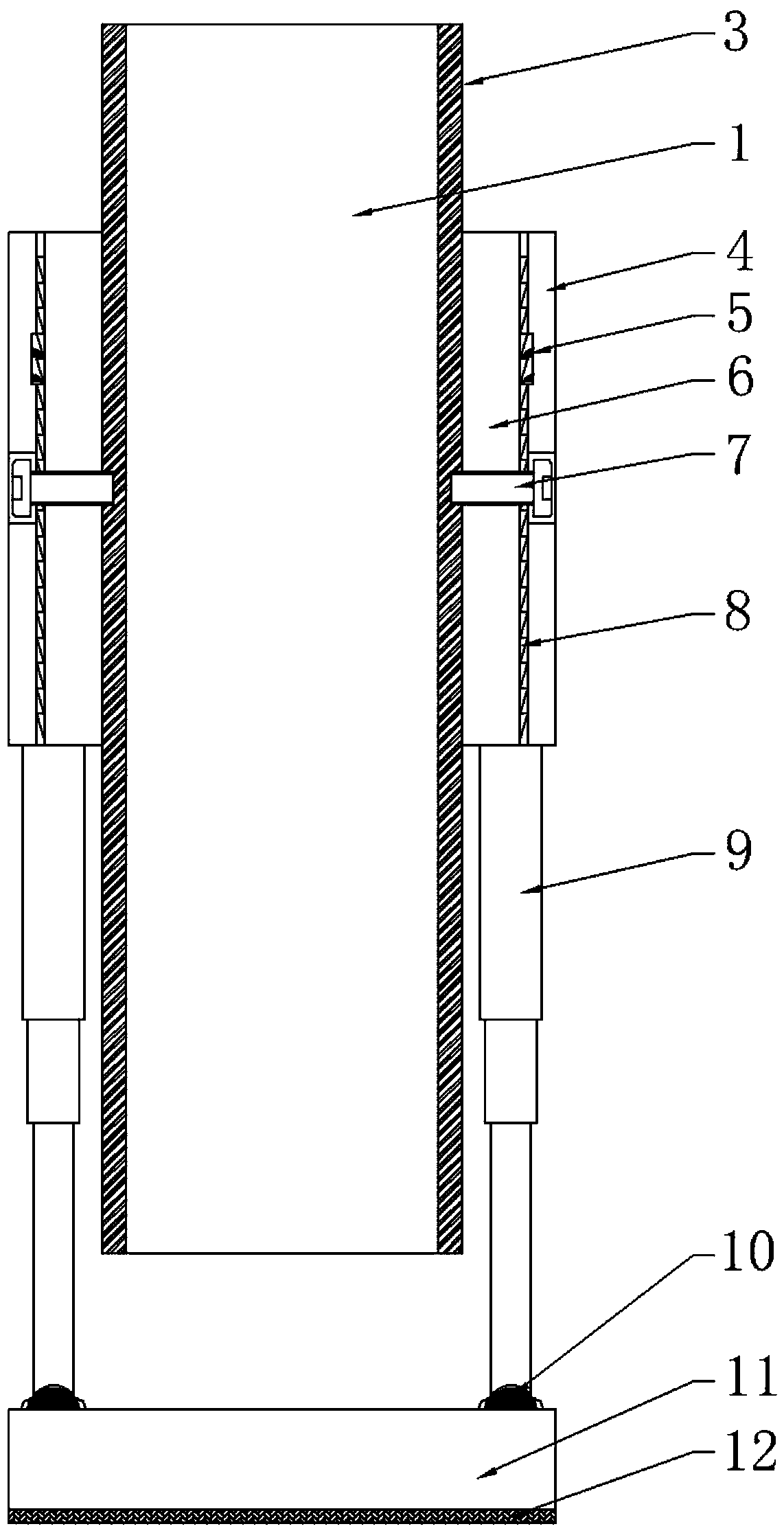
[0025] See figure 1 , figure 2 In this embodiment, the concrete rebound parameter detection device includes a bracket 2. The bracket 2 is provided with three assembly units 4, and the assembly units 4 are equilateral on the bracket 2. In a triangular arrangement, the assembly unit 4 is arranged in an equilateral triangle on the bracket 2, and a fixed frame 6 is provided inside the assembly unit 4. The fixed frame 6 is also an equilateral triangular frame, and the fixed frame 6 is inserted in the assembly unit 4. And can be connected by the sliding groove between the fixed frame 6 and the assembly unit 4. The fixed frame 6 is provided with positioning teeth 8 at the corresponding sliding groove position, and the inner side of the assembly unit 4...


PUM


Abstract

The invention discloses a detection device and a detection method for a rebound parameter of concrete. The device comprises a plurality of concrete rebound hammers and a bracket, wherein the bracket comprises a plurality of assembly units; fixing frames are inserted by the assembly units; then, the concrete rebound hammers are fixedly connected and fixed by the fixing frames; the bracket is connected by extension links and universal joints at the bottom of the bracket; and the connected bracket is leveled by the extension links and the universal joints. The detection device performs detectionby arranging the concrete rebound hammers in a detection area in an equilateral triangle or regular hexagon shape; invalid test values are excluded by sequential detection and simultaneous detection;and the difference of individual measurement is reduced to the full extent. The device can continuously detect the rebound parameter of the concrete, is high in detection precision, high in stabilityand convenient to mount, dismount and adjust at the same time.

Description

Technical field [0001] The invention relates to the technical field of construction engineering testing, in particular to a concrete rebound parameter detection device and a detection method. Background technique [0002] In the field of construction engineering testing technology, the rebound method to detect the compressive strength of concrete is the most commonly used non-destructive testing method in the field inspection of concrete structures. It is mainly realized by the concrete rebound tester as a tool, and the concrete rebound tester is used for on-site inspection. The most extensive non-destructive testing instrument for concrete compressive strength. Its basic principle is to use a tension spring to drive a heavy hammer. The heavy hammer hits the bounce rod perpendicular to the concrete surface with a constant kinetic energy to deform the local concrete and absorb part of the energy. The other part of the energy is converted into the rebound kinetic energy of the heav...

Claims


Application Information

Patent Timeline
Patent Type & Authority Applications(China)
IPC IPC(8): G01N3/52G01N3/02
CPCG01N3/02G01N3/52G01N2203/001G01N2203/0083
Inventor 康建彬李力王新建杨博边祥会许梦兰
Owner 湖南长建科技有限公司
Why Eureka
Try Eureka