
Hall current sensor skeleton

A Hall current and sensor technology, which is applied in the field of sensor skeleton, can solve the problems of poor environmental adaptability and large space occupation, and achieve the effect of reducing the occupied volume, not reducing the accuracy, and improving the environmental adaptability

Active Publication Date: 2019-02-15
SHANDONG INST OF AEROSPACE ELECTRONICS TECH
View PDF6 Cites 1 Cited by
  • Summary
  • Abstract
  • Description
  • Claims
  • Application Information

AI Technical Summary

Problems solved by technology

[0004] In order to solve the technical problems of the Hall current sensor skeleton occupying a large space and poor environmental adaptability in the prior art, the present invention provides a Hall current sensor skeleton

Method used


Image

  • Hall current sensor skeleton
  • Hall current sensor skeleton
  • Hall current sensor skeleton

Examples


Embodiment Construction

[0021] The present invention aims to provide a skeleton of a Hall current sensor to solve the technical problems in the prior art that the skeleton of a Hall current sensor occupies a large space and has poor environmental adaptability.

[0022] In order to enable those skilled in the art to better understand the present invention, the present invention will be further described in detail below in conjunction with specific embodiments and accompanying drawings.

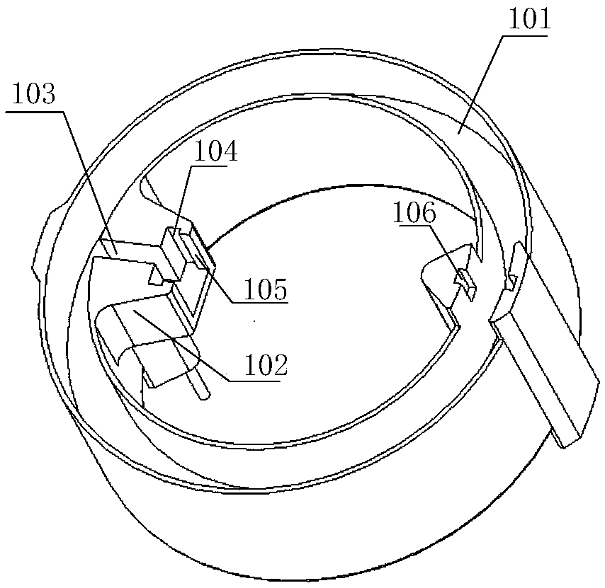
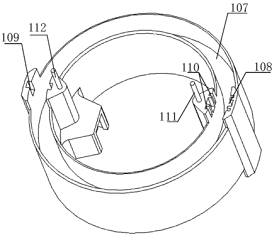
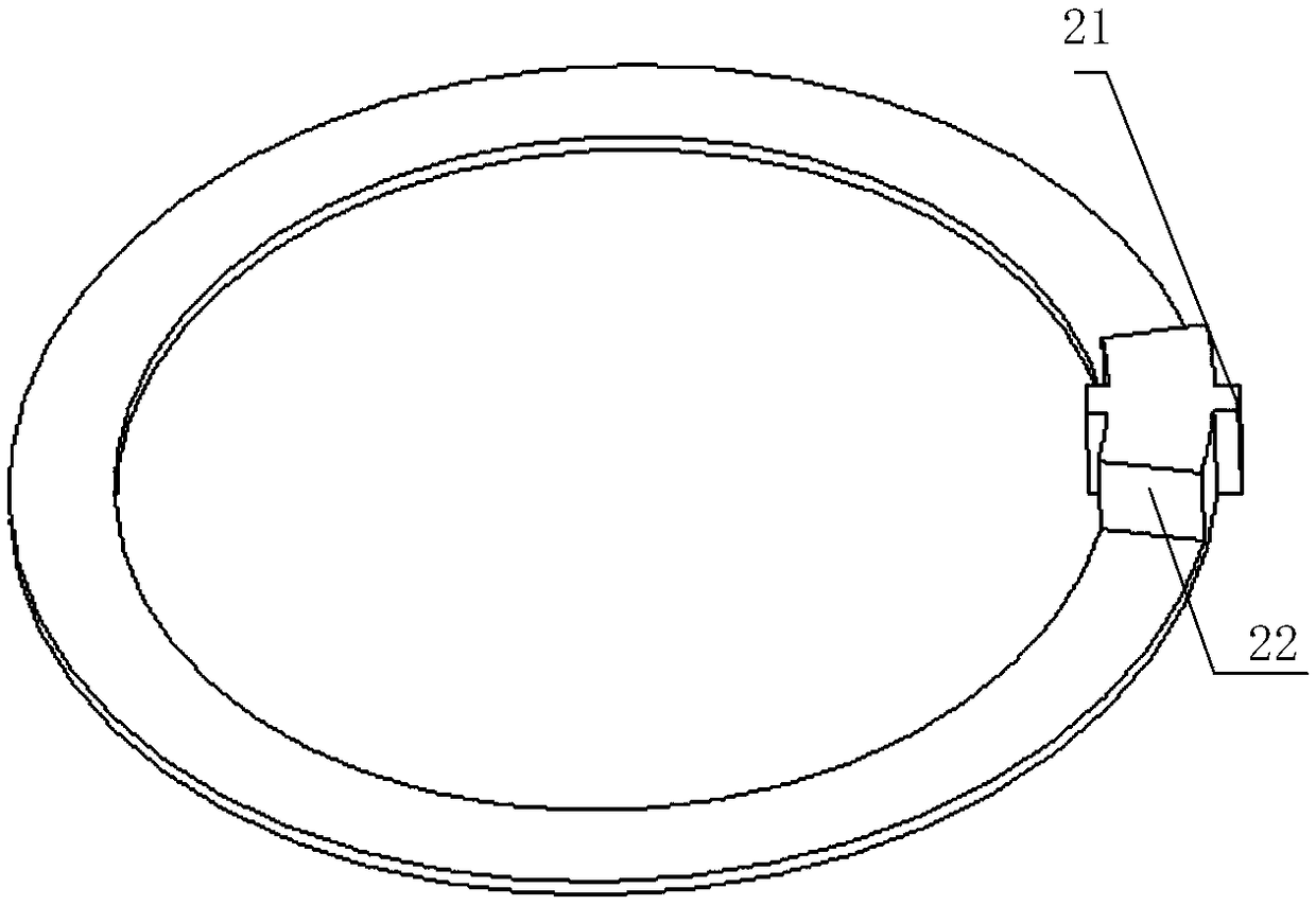
[0023] A Hall current sensor skeleton, comprising a skeleton shell, the upper and lower ends of the skeleton shell are provided with annular magnetic core installation grooves 101 and 107, the upper and lower two annular magnetic core installation grooves are not connected to each other, and are used to install two A coaxial magnetic core, a fixed boss 102 is arranged on the inner wall of the skeleton housing, and a Hall assembly is installed on the fixed boss, and the Hall assembly includes a first Hall element 41, an...


PUM


Abstract

The invention relates to a sensor skeleton, and discloses a Hall current sensor skeleton. The sensor skeleton includes a skeleton shell. The skeleton shell has annular magnetic core mounting grooves in the upper and lower ends thereof. The upper and lower annular magnetic core mounting grooves are not communicated with each other. A fixed boss is arranged on the upper side of the inner wall of theskeleton shell. A Hall component is installed on the fixed boss. The Hall component includes a first Hall element, an adapter plate and an adapter pin. The first Hall element is vertically inserted into and welded on the adapter plate, and is connected with the adapter pin through the adapter plate. The adapter pin is arranged towards the inside of the skeleton shell. The fixed boss includes a first Hall element slot, an adapter plate slot and an adapter pin slot. The width of the adapter plate slot is the same as the width of the adapter plate so that the adapter plate slot and the adapter plate are in close fit with each other. A second Hall element slot is arranged in the lower end face of the outer wall of the skeleton shell. The sensor skeleton is miniaturized, and has strong environmental adaptability.

Description

technical field [0001] The invention relates to a sensor frame, in particular to a Hall current sensor frame. Background technique [0002] The existing high-precision Hall current sensor adopts a double Hall element and a double magnetic core structure mode. Compared with a single Hall element and a single magnetic core mode, its advantage is that it can largely eliminate the position error of the detected current, and at the same time The noise and temperature drift of the sensor output are reduced. [0003] In the existing high-precision Hall current sensor, two magnetic cores are placed parallel and coaxially on the upper and lower sides of the frame, and the two Hall elements are respectively inserted into the air gaps of the two magnetic cores. Among them, the Hall element in the air gap of the upper magnetic core is welded to the adapter board outside the frame, and then transferred to the printed board below the frame. The transfer installation of the Hall element i...

Claims


Application Information

Patent Timeline
IPC IPC(8): G01R1/04
CPCG01R1/04
Inventor 许涛刘强赵旭钟贻兵吕春艳张乐君
Owner SHANDONG INST OF AEROSPACE ELECTRONICS TECH
Learn More