Battery cooling system of new-energy vehicle

A new energy vehicle and heat dissipation system technology, applied in the field of new energy vehicle battery heat dissipation system, can solve the problems of poor heat dissipation effect of new energy vehicle batteries, achieve various heat dissipation methods, prevent accumulation, and improve heat dissipation effect

Inactive Publication Date: 2019-02-15
合肥晓拂新能源有限公司
View PDF0 Cites 0 Cited by
  • Summary
  • Abstract
  • Description
  • Claims
  • Application Information

AI Technical Summary

Problems solved by technology

[0003] Aiming at the problem of poor heat dissipation effect of new energy vehicle batteries in the prior art, the purpose of the present invention is to provide a new energy vehicle battery heat dissipation system

Method used


Image

  • Battery cooling system of new-energy vehicle
  • Battery cooling system of new-energy vehicle
  • Battery cooling system of new-energy vehicle

Examples


Embodiment 1

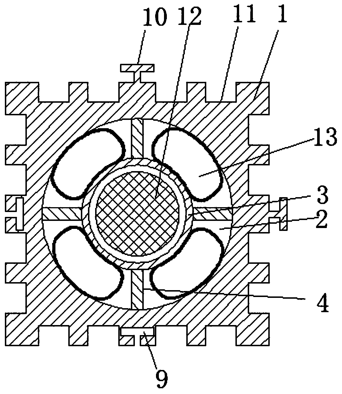
[0027] Such as figure 1 , figure 2 and Figure 6 As shown, a new energy vehicle battery heat dissipation system includes a battery packaging structure and a cooling system. The battery packaging structure includes a body 1, and the body 1 is used as a housing of the packaging structure. The ends respectively pass through the opposite ends of the body 1, and the cavity 2 is provided with a battery carrying device 3 for placing the battery. The battery carrying device 3 is made of a heat-conducting material. The ventilation channel is provided with a fixing part 4, and the battery carrying device 3 is connected to the inner wall of the cavity 2 through the fixing part 4; the ventilation channel is provided with a water storage bag 13 made of elastic heat-conducting material, and the water storage bag 13 is provided with an inlet The water port and the water outlet, and the water storage bag 13 are fixedly connected on the inner wall of the cavity 2 .

[0028] In this embodim...

Embodiment 2

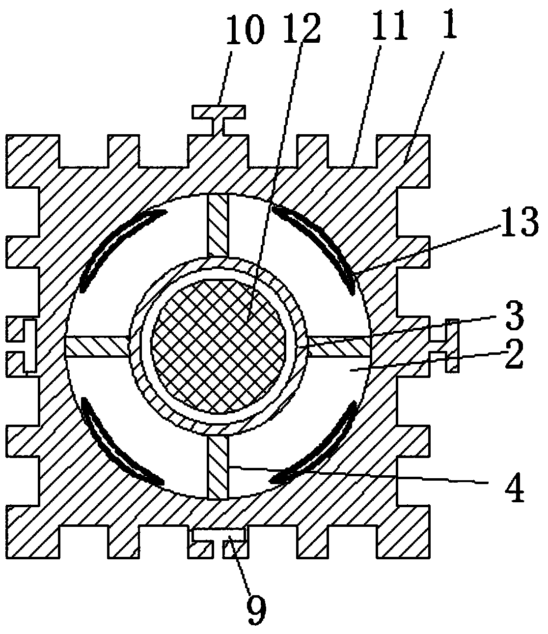
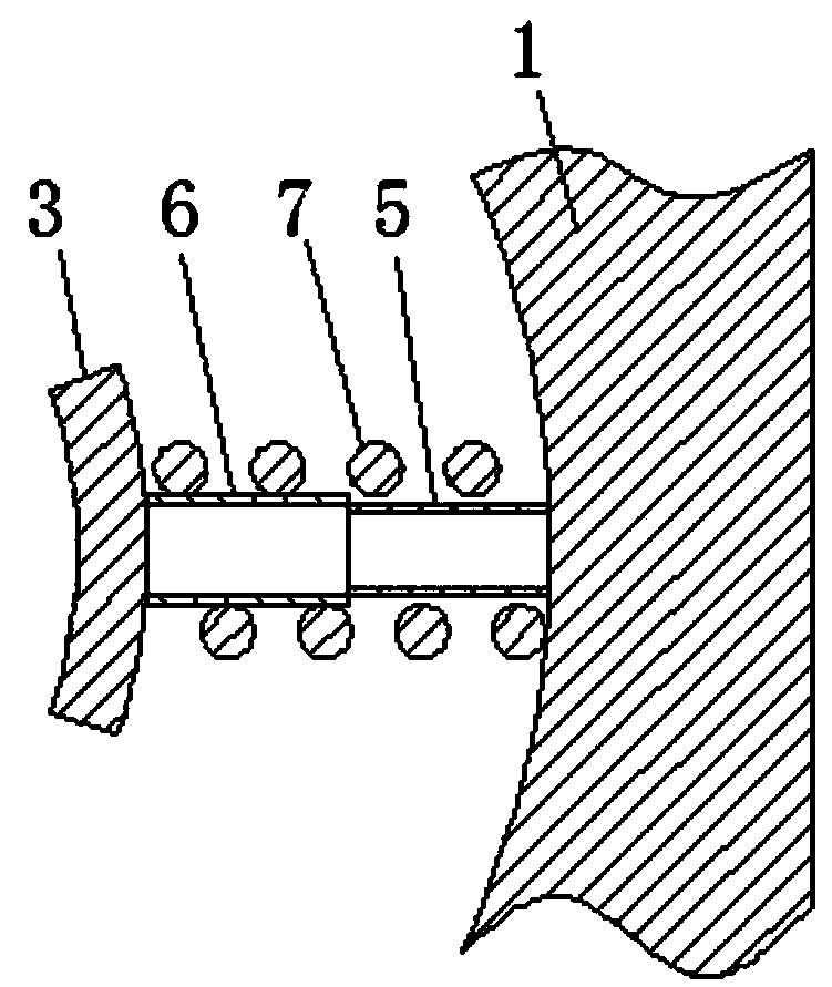
[0035] Such as image 3 As shown, the difference between it and Embodiment 1 is that in this embodiment, there are several fixing parts 4, and the several fixing parts 4 are evenly spaced in the circumferential direction, and two adjacent fixing parts 4 are provided with There is a water storage bag 13; the fixed part 4 is a telescopic rod, and the telescopic rod includes a fixed joint 5 fixedly connected to the inner wall of the cavity 2 and a movable joint 6 sleeved on the fixed joint 5, and the telescopic joint A spring 7 is sleeved on the telescopic rod, and one end of the spring 7 is fixedly connected with the fixed section 5 or the inner wall of the cavity 2 , and the other end is fixedly connected with the movable section 6 .

[0036] The above arrangement enables the battery carrying device 3 to move, so that the shock absorption of the battery 12 can be realized, and the battery 12 can be prevented from being damaged by vibration.

Embodiment 3

[0038] Such as Figure 4 As shown, the difference between it and the second embodiment is that this embodiment provides another shock absorbing structure for the battery 12 of the fixing member 4; the fixing member 4 includes a slide bar, and the inner wall of the cavity 2 is provided with a A spring 7 is connected between the sliding hole 8 and the inner wall of the cavity 2 .


PUM


Abstract

The invention discloses a battery cooling system of a new-energy vehicle and belongs to the field of new energy. The battery cooling system comprises a battery packaging structure and a cooling system, wherein the battery packaging structure comprises a body, a cavity is formed in the body, two ends of the cavity penetrates two opposite ends of the body respectively, a battery bearing device for battery placement is arranged in the cavity and made of a heat conductive material, a ventilating channel is formed between the outer wall of the battery bearing device and the inner wall of the cavity, fixing pieces are arranged in the ventilating channel, and the battery bearing device is connected to the inner wall of the cavity through the fixing pieces; water storage bags made of an elastic heat conductive material are arranged in the ventilating channel, and each water storage bag is provided with a water inlet and a water outlet and is connected to the inner wall of the cavity; the cooling system comprises an air cooling system connected with the ventilating channel and a water cooling system connected with the water storage bags. The battery cooling system is simple in structure andreasonable in design and can effectively cool a battery.

Description

technical field [0001] The invention relates to the field of new energy, in particular to a cooling system for a battery of a new energy vehicle. Background technique [0002] An electric vehicle (BEV) refers to a vehicle that is powered by a vehicle-mounted power supply, drives the wheels with a motor, and meets the requirements of road traffic and safety regulations. Due to its smaller impact on the environment than traditional cars, its prospects are widely optimistic. As the power source of electric vehicles - battery, its current main cooling methods include: natural cooling, air cooling and liquid cooling. However, in the existing battery packaging structure, the battery cooling method has problems such as poor cooling effect and high cooling cost. Therefore, how to design a packaging structure and battery cooling system for electric vehicle battery packs with good heat dissipation performance is an urgent problem to be solved in the industry. Contents of the inven...

Claims


Application Information

Patent Timeline
Patent Type & Authority Applications(China)
IPC IPC(8): H01M2/10H01M10/613H01M10/625H01M10/6563H01M10/6567H01M50/249
CPCH01M10/613H01M10/625H01M10/6563H01M10/6567H01M50/20Y02E60/10
Inventor 李致
Owner 合肥晓拂新能源有限公司
Why Eureka
Try Eureka