Automatic deicing device for overhead transmission line

An overhead transmission line, automatic technology, applied in overhead installation, cable installation, electrical components and other directions, can solve the problems of tower tilt, reduce transmission efficiency, collapse and broken insulator flashover, etc., to achieve accurate and enhanced opening angle control. Practicality, the effect of improving safety

Pending Publication Date: 2019-02-15
HEBEI UNIV OF TECH
View PDF2 Cites 14 Cited by
  • Summary
  • Abstract
  • Description
  • Claims
  • Application Information

AI Technical Summary

Problems solved by technology

Due to the severe icing phenomenon of power grids in central China, east China and southern China, it will cause the towers carrying ultra-high and ultra-high voltage transmission lines to tilt, collapse and disconnection, and insulator flashover, which will cause tripping and power supply of transmission lines. Interruptions and other accidents have seriously affected industrial and agricultural production and people's lives
[0003] Due to the harsh and complicated working environment for line deicing, methods such as external force beating and high current melting are mainly used for deicing at home and abroad. The time consumption and cost are large, and the above methods have great limitations
[0004] Patent Publication No. "CN107516865A" "A Power Transmission Line Deicer" invention patent adopts traveling drive and deicing part a

Method used


Image

  • Automatic deicing device for overhead transmission line
  • Automatic deicing device for overhead transmission line
  • Automatic deicing device for overhead transmission line

Examples


Embodiment Construction

[0030] Embodiments of the present invention will be described in further detail below in conjunction with the accompanying drawings.

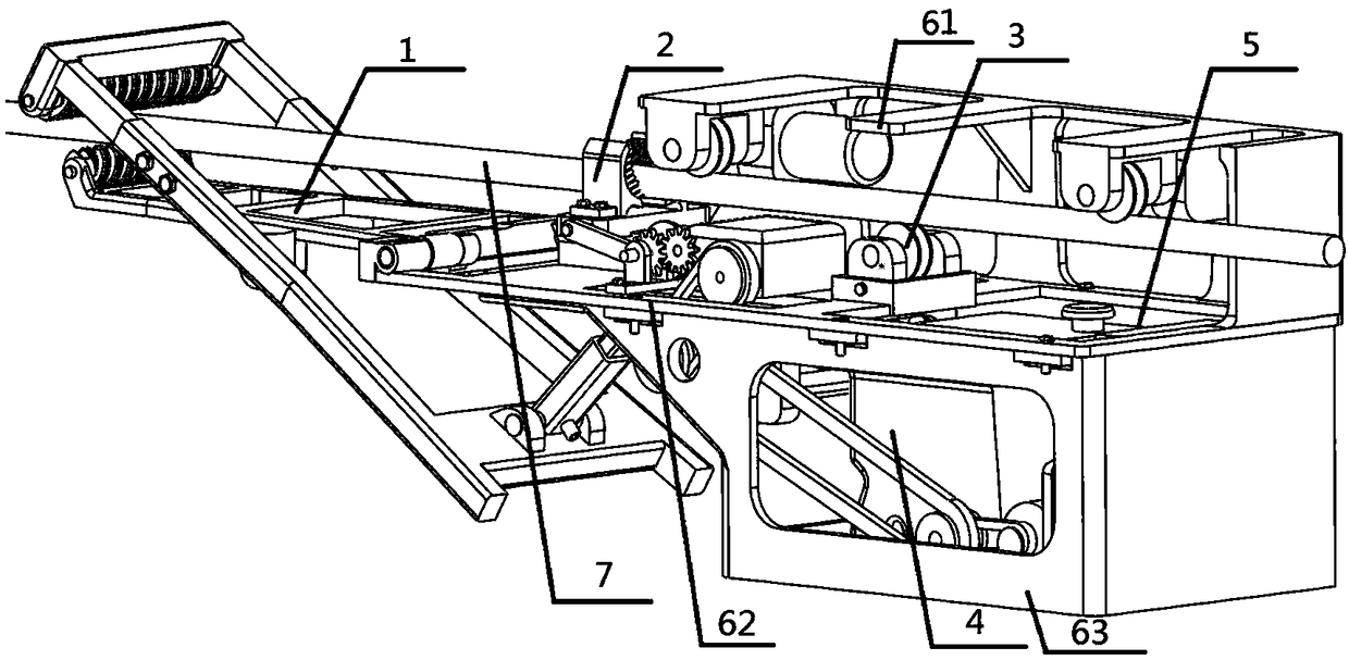
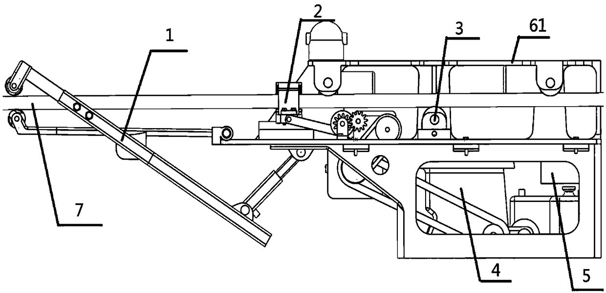
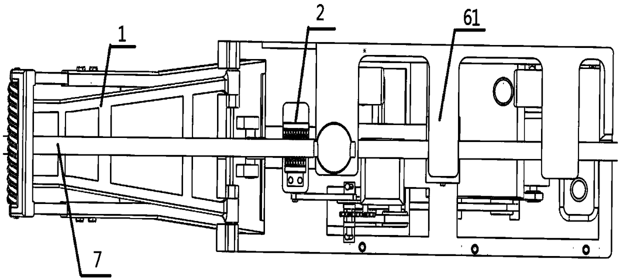
[0031] An automatic deicing device for overhead transmission lines, such as Figure 1 to Figure 3 and Figure 8As shown, it includes a first deicing mechanism 1, a second deicing mechanism 2, a traveling mechanism 3, a power mechanism 4, a control mechanism 5, a power module 8, an oil tank 9 and a set of mounting plates. The mounting plate includes an upper mounting plate 61, a middle mounting plate 62 and a lower mounting plate 63 installed together from top to bottom; the travel mechanism 3 is installed on the upper end of the middle mounting plate 62, and the first deicing mechanism 1 is installed in the middle The front end of the mounting plate 62, the wire 7 runs through the middle of the first deicing mechanism, the second deicing mechanism 2 is installed in the middle of the middle mounting plate 62, and the other end of the second dei...


PUM


Abstract

The invention relates to an automatic deicing device for an overhead transmission line. The automatic deicing device comprises two deicing mechanisms, an advancing mechanism, a power mechanism, a control mechanism, a power supply module, an oil tank and an installation plate, wherein the installation plate comprises an upper installation plate, a middle installation plate and a lower installationplate, and the upper installation plate, the middle installation plate and the lower installation plate are connected through bolts from top to bottom; the advancing mechanism is installed on the upper end of the middle installation plate; the first deicing mechanism is installed on the front end of the middle installation plate and penetrates through a traverse; the second deicing mechanism is installed in the middle of the middle installation plate and is also connected with the power mechanism; the power mechanism and the control mechanism are both installed on the upper end of the lower installation plate; and the control mechanism comprises a video surveillance module installed on the upper installation plate, and a control cabinet installed on the lower installation plate. The deviceis reasonable in design, has a good deicing effect, can improve the power supply reliability of an electric power system, reduces the workloads of workers, lowers energy consumption, has a simple andpractical integral structure, has a stable working state, and is convenient in disassembling and repairing.

Description

technical field [0001] The invention belongs to the technical field of power transmission lines, in particular to an automatic deicing device for overhead power transmission lines. Background technique [0002] At present, there are more and more ultra-high and ultra-high voltage transmission lines. Due to the severe icing phenomenon of power grids in central China, east China and southern China, it will cause the towers carrying ultra-high and ultra-high voltage transmission lines to tilt, collapse and disconnection, and insulator flashover, which will cause tripping and power supply of transmission lines. Interruptions and other accidents have seriously affected industrial and agricultural production and people's lives. [0003] Due to the harsh and complicated working environment for line deicing, methods such as external force beating and high current melting are mainly used for deicing at home and abroad. The time consumption and cost are large, and the above methods ...

Claims


Application Information

Patent Timeline
IPC IPC(8): H02G7/16
CPCH02G7/16
Inventor 李玲玲常云彪陈文泉张婵黄君胜冯鑫虎
Owner HEBEI UNIV OF TECH
Why Eureka
Try Eureka