
Rubber belt shearing device and method

A technology of shearing device and rubber belt, which is applied in metal processing and other directions, can solve the problems of unfixable rubber belt, low cutting precision, and low production efficiency, and achieve the effects of reducing labor costs, improving work efficiency, and operating safety

Inactive Publication Date: 2019-02-19
微芒果软件(大连)有限公司
View PDF0 Cites 0 Cited by
  • Summary
  • Abstract
  • Description
  • Claims
  • Application Information

AI Technical Summary

Problems solved by technology

[0002] There are many kinds of rubber products, but the production process is basically the same. The basic process of rubber products using general solid rubber—raw rubber as raw material includes six basic processes: mastication, mixing, calendering, extrusion, molding, and vulcanization. Of course, basic processes such as raw material preparation, finished product sorting, inspection and packaging are also indispensable. At present, the cutting part of the finished rubber belt is still done manually. Since the rubber belt cannot be fixed, the cutting accuracy is low, poor cutting is prone to occur, and the production efficiency is low.

Method used


Image

  • Rubber belt shearing device and method
  • Rubber belt shearing device and method
  • Rubber belt shearing device and method

Examples


Embodiment 1

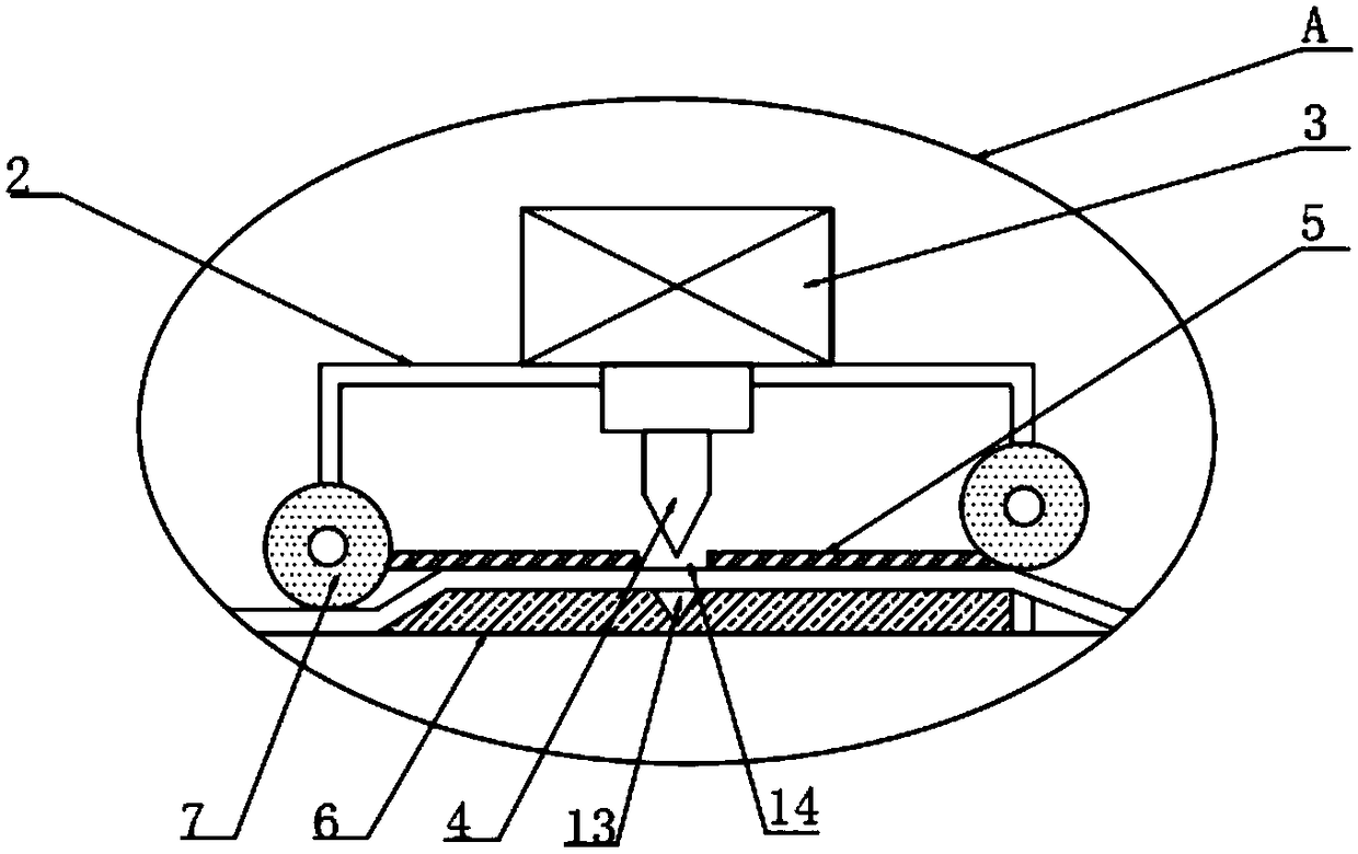
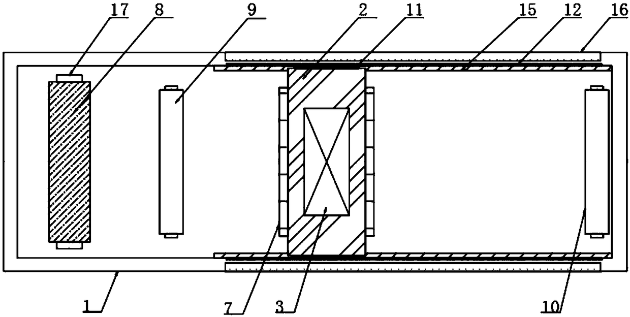
[0025] The present invention provides Figure 1-3 The rubber belt shearing device shown includes a workbench 1, a fixed block 2 is arranged on the top of the workbench 1, an electric push rod 3 is arranged on the top of the fixed block 2, and an output shaft of the electric push rod 3 is arranged There is a cutter 4, the bottom of the cutter 4 is provided with a compression block 5, which is convenient for pressing and fixing the rubber band, the bottom of the fixed block 2 is provided with a backing plate 6, and the fixed block 2 has an inlet and an outlet Each is provided with a first electric roller 7, a roller 8 is arranged on one side of the fixed block 2, a second electric roller 9 is arranged between the roller 8 and the fixed block 2, and the other side of the fixed block 2 is arranged There is a third electric roller 10 to facilitate the movement of the rubber belt.

[0026] Further, in the above technical solution, the fixing block 2 is provided with a clamping block 11...

Embodiment 2

[0035] A rubber belt cutting method, including the rubber belt cutting device, further comprises the following steps:

[0036] S1: The rubber band can enter the inside of the fixed block 2;

[0037] S2: Both the inlet and outlet of the fixed block 2 are provided with a first electric roller 7 to push the rubber belt;

[0038] S3: The electric push rod 3 is fixed on the top of the fixed block 2, and the output shaft of the electric push rod 3 penetrates the fixed block 2;

[0039] S4: The first electric roller 7 is opened to tighten the rubber belt;

[0040] S5: The cutter 4 cuts the rubber band through the slot 14.


PUM


Abstract

The invention discloses a rubber belt shearing device and method. The rubber belt shearing device comprises a worktable; the top part of the worktable is provided with a fixed block; the top part of the fixed block is provided with an electric pushing rod; an output shaft of the electric pushing rod is provided with a cutter; the bottom part of the cutter is provided with a compressing block; thebottom part of the fixed block is provided with a base plate; a feeding hole and a discharge hole of the fixed block are each provided with a first electric roller; one side of the fixed block is provided with a roller; a second electric roller is arranged between the roller and the fixed block; and the other side of the fixed block is provided with a third electric roller. According to the rubberbelt shearing device and method disclosed by the invention, the fixed block, the compressing block and the base plate are arranged, wherein the compressing block is capable of guaranteeing that the surface of a material being processed is flat without creases; and the feeding hole and the discharge hole of the fixed block are each provided with the first electric roller, and the first electric rollers are capable of tensioning the material being processed, so that cutting the material being processed tidily by the cutter is facilitated.

Description

Technical field [0001] The invention relates to the technical field of large-scale and precise rubber-plastic equipment processing equipment and mold manufacturing, in particular to a rubber belt shearing device and method. Background technique [0002] There are many types of rubber products, but the production process is basically the same. The basic process of rubber products using general solid rubber-raw rubber as raw material includes: plasticizing, mixing, calendering, pressing, molding, and vulcanizing 6 basic processes Of course, basic processes such as raw material preparation, finished product finishing, inspection and packaging are also indispensable. At present, the post-cutting part of the rubber belt is finished manually. Because the rubber belt cannot be fixed, the cutting accuracy is low, poor cutting is prone to occur, and production efficiency is low. [0003] Therefore, it is necessary to invent a rubber belt cutting device and method to solve the above problems...

Claims


Application Information

Patent Timeline
Patent Type & Authority Applications(China)
IPC IPC(8): B26D1/08B26D7/14B26D7/00
CPCB26D1/085B26D7/00B26D7/14
Inventor 伊燕
Owner 微芒果软件(大连)有限公司
Learn More