Level control and drainage device

A drainage device and water level control technology, applied in water supply devices, flushing toilets, sanitary equipment for toilets, etc., can solve the problems of indetermination of the position of the shaft, the volume of the space occupied by the water tank, and small drainage gaps, etc., to avoid bacteria and Virus spread, bathroom space saving, water noise elimination effect

Pending Publication Date: 2019-02-19
深圳异次方科技有限公司
View PDF0 Cites 6 Cited by
  • Summary
  • Abstract
  • Description
  • Claims
  • Application Information

AI Technical Summary

Problems solved by technology

The disadvantages of the supporting water tank further include: a. The user needs to wait for the water tank to be filled with water before flushing again after each flush; b. The space occupied by the water tank; c. The cost and maintenance cost of the water tank and supporting accessories; d. . Water tank pipes often leak, causing a lot of waste of water, damage to furniture and property; The excrement in the body floats in the sewage, and the gas in the cavity leaks out. The scene on the scene is embarrassing and nauseating, which is time-consuming and inconvenient
[0008] 3. When the siphon effect of the elbow-shaped sewage channel disappears, the air enters the pipe channel. Since the pipe channel is vertical, when the water level in the channel drops, the air enters and exits the pipe channel. The noise generated by liquid, air velocity and water collision with the pipe wall is easy to wake people up in the middle of the night when it is quiet.
[0010] 5. The water level in the flush toilet is maintained at a fixed level. When people defecate, when the solid objects fall, the water often collides with the water due to the high water level, and the water splashes back, splashing the skin, and the result of splashing is very annoying.
[0014] The push-type plug is easy to block due to the small drainage gap and slow water flow rate. Users often need to reach into the water with their hands to help the plug gap unblock, which is easy to splash and splash water to stain and wet the clothes, face, hands, etc.;
[0015] Because the shaft of the flip plug can slide in the shaft track, the user often cannot determine the position of the shaft of the flip plug at the bottom of the water, and needs to repeatedly use fingers or small sticks to move along the bottom of the water. The side of the flip-type water stopper is pressed and knocked hard, which often splashes and splashes water to stain and wet the clothes, face, hands, etc., which is time-consuming and inconvenient
[0016] Therefore, the plug-in plugs, push-type plugs and flip-type plugs of the prior art that can only realize drainage and water storage functions can no longer meet people's requirements. The height of the water level and the device for convenient storage and drainage of household washing containers such as basins, washbasins, and bathtubs

Method used


Image

  • Level control and drainage device

Examples


specific Embodiment approach 1

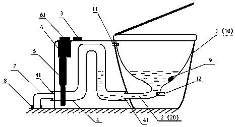
[0038] The embodiment of the present invention provides a water level control and drainage device, including a toilet body 1, a flush valve 3, a U-shaped pipe 4, a toilet sewage outlet 2, a sewage pipe connecting pipe 7, a motor 6, and an ultrasonic generator 9. Body 1 is a conventional prior art toilet, with an upper water outlet 11 at the inner side wall of the upper end, and a lower water outlet 12 at the inner side of the lower end aligned with the center of the toilet sewage outlet 2; Protruding spring sealing ring 41, one end of which is in sealing and movable connection with the toilet sewage outlet 2, and the other end is in sealing and moving connection with the sewage pipe connecting pipe 7, and the spring sealing ring 41 can be rotated more than 1 million times to maintain the sealing degree; One end of the U-shaped pipe 4 is provided with a transmission device 5, which can be one or more combinations of transmission structures such as gears, transmission shafts, and...

specific Embodiment approach 2

[0043]The embodiment of the present invention provides a water level control and drainage device, which is basically the same as the specific embodiment 1, except that it is not the toilet sewage discharge and cleaning, but the washbasin sewage discharge and cleaning, including corresponding to the toilet body 1 in the specific embodiment 1 Washbasin body 10, washbasin drain outlet 20 corresponding to toilet drain outlet 2, U-shaped pipe 4, transmission device 5, sewage pipe connecting pipe 7, motor 6 or manual rotary valve 61, ultrasonic generator 9. The bottom of the washbasin basin body 10 is provided with a washbasin drain outlet 20, and at least one circle of protruding spring sealing ring 41 is respectively installed on the walls at both ends of the U-shaped pipe 4, and one end of the U-shaped pipe 4 is connected to the washbasin drain outlet 20. Sealed movable connection, the other end is sealed and movable connected with the sewage pipe connecting pipe 7; one end of the...


PUM


Abstract

The invention provides a level control and drainage device. The level control and drainage device comprises a toilet body, a flushing valve, a U-shaped pipe, a toilet sewage outlet, a sewage pipe connecting pipe, a motor and an ultrasonic generator and is characterized in that one end of the U-shaped pipe is movably connected in a sealed mode with the toilet sewage outlet, the other end of the U-shaped pipe is movably connected in a sealed mode with the sewage pipe connecting pipe, and the U-shaped pipe can be in shaft rotation at the connecting part between the toilet sewage outlet and the sewage pipe connecting pipe during application to change the top height and further to control the height of water seal inside the toilet body. Therefore, the level control and drainage device saves a traditional toilet water tank to greatly reduce water required for toilet flushing as well as flushing noise, and avoids waiting for replenishing water into the water tank; during application, the water seal of the toilet body can be adjusted to the top of the toilet body, so that internal comprehensive cleaning through ultrasonic waves can be facilitated. The level control and drainage device is also applicable to containers such as washing basins and is simple in structure and economically feasible.

Description

technical field [0001] The invention relates to excrement and water discharge treatment technology, in particular to a water level control and drainage device. Background technique [0002] The official name of flush toilet is flush toilet. In 1775, a watchmaker named Alexander Cummings in London developed a flush toilet and obtained a patent for the first time. In 1889, Thomas Crapper, a British plumber, invented a flush toilet with an elbow structure. The height of the water level in the toilet body is fixed by the height of the inner tube channel of the fixed elbow structure of the toilet. The flush toilet with elbow structure uses a water storage tank and a floating ball to flush water. When flushing, a sufficient amount of water is sent from the water storage tank into the toilet body within a few seconds. First, the water level in the toilet body must be quickly raised to exceed the toilet At a certain height of the water level at the highest end of the pipe channel ...

Claims


Application Information

Patent Timeline
Patent Type & Authority Applications(China)
IPC IPC(8): E03D9/00E03D11/02E03D11/13
CPCE03D9/002E03D11/02E03D11/13
Inventor 胡鼎峯温燕铭
Owner 深圳异次方科技有限公司
Why Eureka
Try Eureka