
Short-time fuel oil cooling system for aero-engine

A cooling system and fuel technology, which is applied to engine components, machines/engines, turbine/propulsion fuel delivery systems, etc., can solve problems such as short-term over-temperature in the fuel cooling system, achieve poor heat dissipation, achieve cooling, and avoid coking Effect

Active Publication Date: 2019-02-19
AECC SHENYANG ENGINE RES INST
View PDF11 Cites 6 Cited by
  • Summary
  • Abstract
  • Description
  • Claims
  • Application Information

AI Technical Summary

Problems solved by technology

[0004] The purpose of this application is to provide a short-term fuel cooling system for aero-engines to solve the short-term overtemperature problem of aero-engine fuel cooling systems

Method used


Image

  • Short-time fuel oil cooling system for aero-engine
  • Short-time fuel oil cooling system for aero-engine
  • Short-time fuel oil cooling system for aero-engine

Examples


Embodiment Construction

[0033] In order to make the purpose, technical solution and advantages of the application more clear, the technical solution in the embodiment of the application will be described in more detail below in conjunction with the drawings in the embodiment of the application. In the drawings, the same or similar reference numerals denote the same or similar elements or elements having the same or similar functions throughout. The described embodiments are some, but not all, embodiments of the application. The embodiments described below by referring to the figures are exemplary, and are intended to explain the present application, and should not be construed as limiting the present application. Based on the embodiments in this application, all other embodiments obtained by persons of ordinary skill in the art without creative efforts fall within the protection scope of this application. Embodiments of the present application will be described in detail below in conjunction with th...


PUM

PropertyMeasurementUnit
Diameteraaaaaaaaaa

Abstract

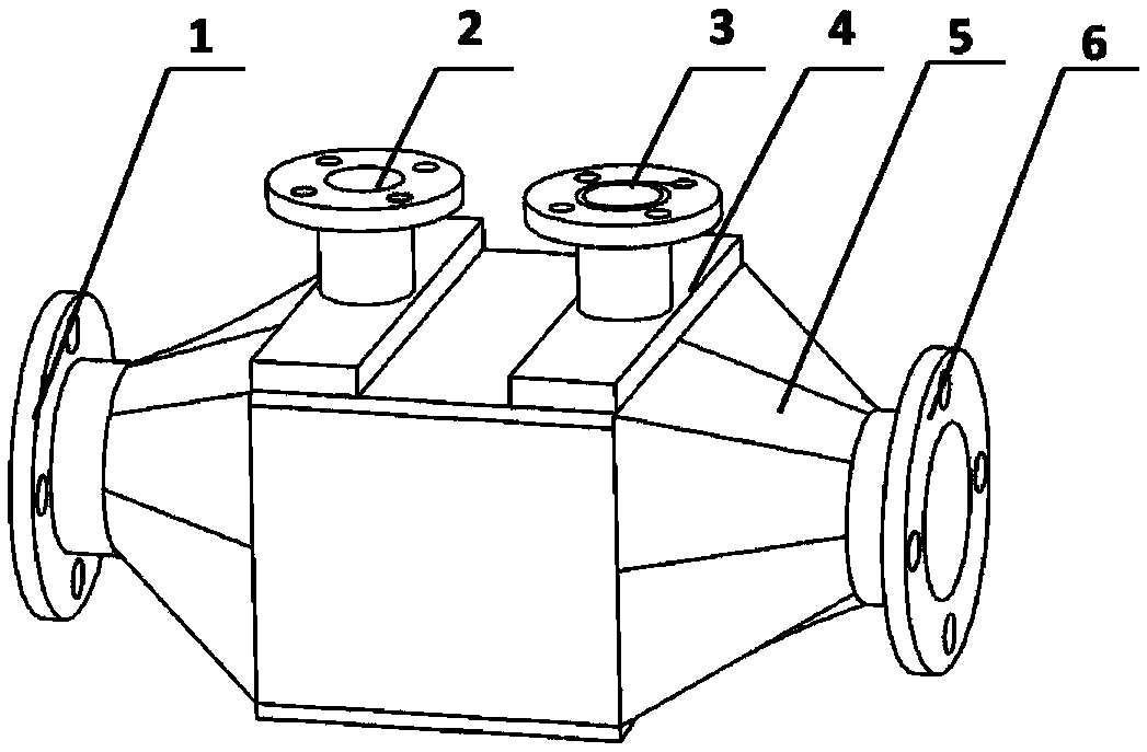
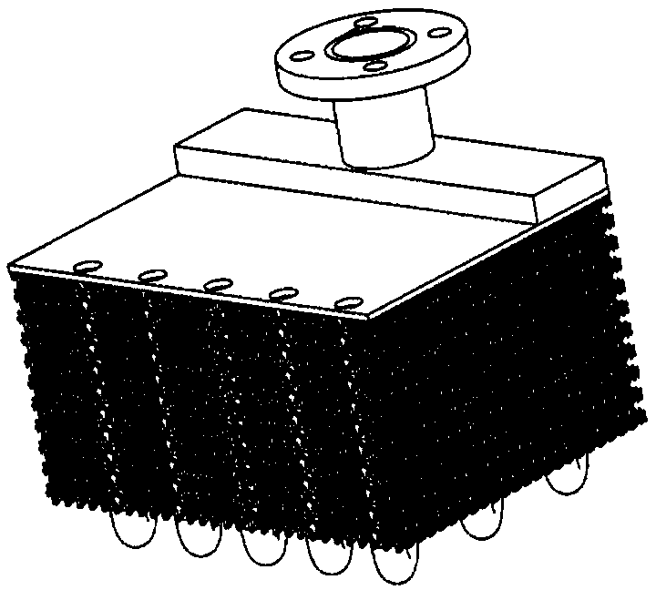
The invention belongs to the technical field of cooling systems, and particularly relates to a short-time fuel oil cooling system for an aero-engine. A liquid nitrogen-fuel oil heat exchanger is adopted in the cooling system, the temperature of fuel oil is monitored through a resistance temperature detector, the flow of liquid nitrogen is controlled through a temperature sensing valve, the fuel oil is cooled, short-time cooling of the engine fuel oil is achieved, the problem that the cooling effect in the engine is not good at the take-off stage of an airplane at high temperature is solved, and coking of the engine fuel oil is avoided.

Description

technical field [0001] The application belongs to the technical field of cooling systems, in particular to a short-time fuel cooling system for aero-engines. Background technique [0002] With the continuous improvement of the thrust and Mach number of the aero-engine, the heat dissipation inside the engine is increasing, and the heat load borne by the engine fuel system is increasing. Especially when the aircraft takes off in high-temperature weather, the engine fuel system will The contradiction between the cooling capacity provided and the heat dissipation requirements inside the engine is particularly prominent, which will lead to the inability to release the heat dissipation inside the engine, overheating of internal components, overheating of fuel, and even coking to block pipes and nozzles. [0003] Therefore, it is desirable to have a technical solution to overcome or at least alleviate at least one of the above-mentioned drawbacks of the prior art. Contents of the...

Claims


Application Information

Patent Timeline
IPC IPC(8): F02C7/141F02C7/22
CPCF02C7/141F02C7/22
Inventor 庞晓冬梁义强李洪莲于霄陆海鹰姜楠赵孟张筱喆杜慧鹏
Owner AECC SHENYANG ENGINE RES INST
Learn More