
Experimental and analytical method for shaft system vibration of reciprocating equipment

A technology for shafting vibration and analysis methods, which is applied in vibration testing, measuring devices, testing of machine/structural components, etc., and can solve the problems of difficult quantitative analysis of shafting vibration factors, complex shafting of reciprocating equipment, and difficulty in extracting information.

Active Publication Date: 2019-02-19
INST OF SINOPEC OILFIELD EQUIP CORP +1
View PDF5 Cites 1 Cited by
  • Summary
  • Abstract
  • Description
  • Claims
  • Application Information

AI Technical Summary

Problems solved by technology

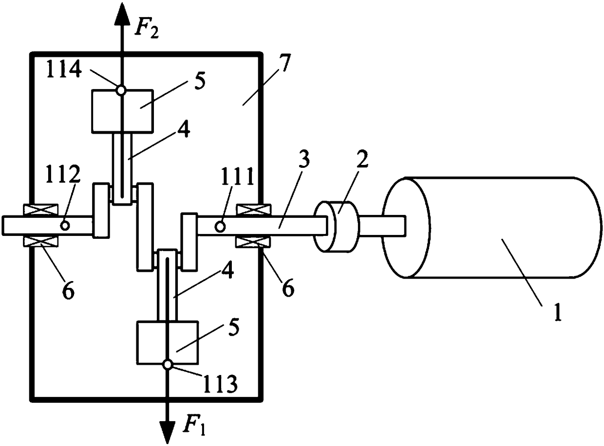
[0004] However, the shaft system of reciprocating equipment is more complex than that of centrifugal rotating equipment. At present, there are still some limitations when evaluating the state of the shaft system by collecting lateral vibration signals and torsional vibration signals
For example, the vibration signal measured at the 6 parts of the bearing includes the vibration information of the bearing, crankshaft, connecting rod, etc., and it is very difficult to extract the information of a certain part from it. Therefore, it is difficult to quantitatively analyze the influence of the vibration factors of the shaft system

Method used


Image

  • Experimental and analytical method for shaft system vibration of reciprocating equipment
  • Experimental and analytical method for shaft system vibration of reciprocating equipment
  • Experimental and analytical method for shaft system vibration of reciprocating equipment

Examples


Embodiment Construction

[0073] The present invention will be further described in detail below in conjunction with the accompanying drawings, so that those skilled in the art can implement it with reference to the description.

[0074] It should be noted that the experimental methods described in the following embodiments, unless otherwise specified, are conventional methods, and the reagents and materials, if not otherwise specified, can be obtained from commercial sources; in the description of the present invention, The terms "landscape", "portrait", "top", "bottom", "front", "rear", "left", "right", "vertical", "horizontal", "top", "bottom", The orientation or positional relationship indicated by "inner", "outer", etc. is based on the orientation or positional relationship shown in the drawings, which is only for the convenience of describing the present invention and simplifying the description, and does not indicate or imply that the referred device or element must have Certain orientations, co...


PUM


Abstract

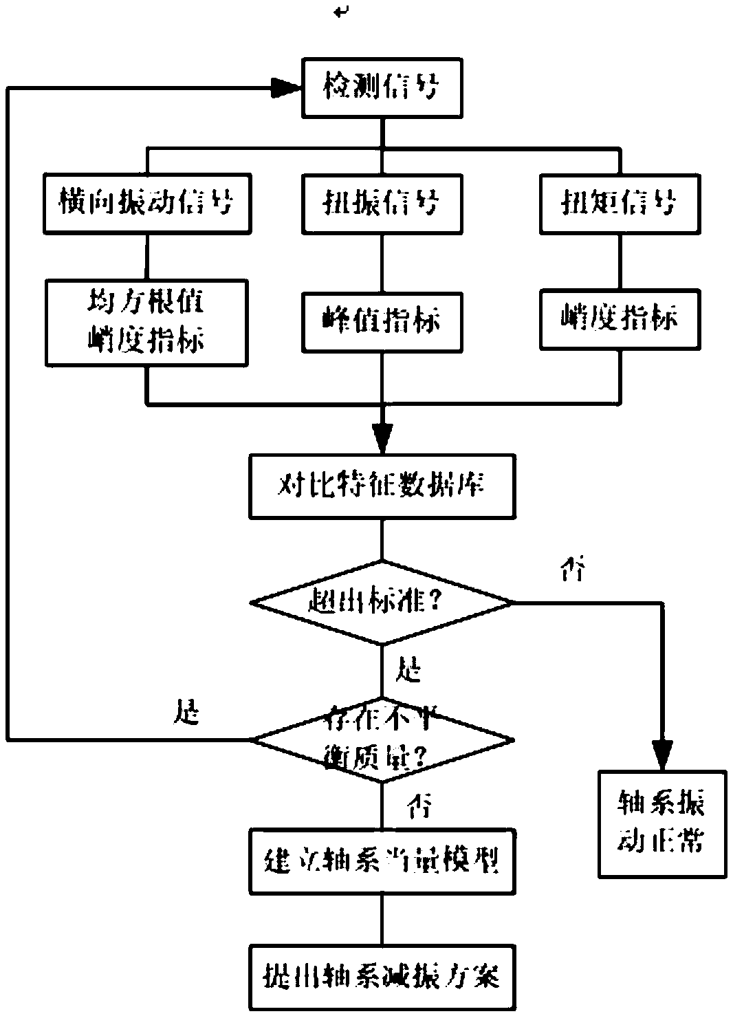
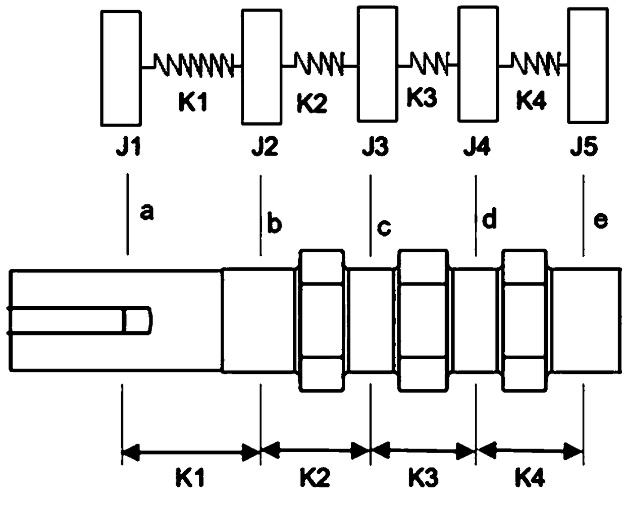
The invention discloses an experimental and analytical method for shaft system vibration of reciprocating equipment. The experimental and analytical method comprises the following steps that S1, a comparison characteristic database of a standard shaft system is established; S2, under the working rotating speed of a to-be-detected shaft system, a root-mean-square value kurtosis index X<RMS1>, a peak index B1 and a kurtosis index K1 are obtained; S3, the X<RMS1>, the B1 and the K1 which are obtained in the step S2 are compared with a root-mean-square value kurtosis index X<RMSs>, a peak index Bsand a kurtosis index Ks in the comparison characteristic database of the standard shaft system under the working rotating speed; S4, whether the to-be-detected shaft system is unbalanced in mass or not is analyzed; and S5, an equivalent model of the to-be-detected shaft system is established, and a shaft system vibration-reduction scheme is put forward. According to the experimental and analytical method for shaft system vibration of the reciprocating equipment, analyzing is conducted in the aspects of detecting means, signal processing and characteristic database establishing, and guidance is provided for unbalanced vibration excitation of a shaft system of the reciprocating equipment and detecting and analyzing of a resonance zone.

Description

technical field [0001] The invention relates to the technical field of shaft system vibration detection of reciprocating equipment. More specifically, the present invention relates to a vibration experiment and analysis method of a reciprocating equipment shaft system. Background technique [0002] The shafting vibration of reciprocating equipment is very complicated, and there are many influencing factors, such as unbalanced excitation force on the shafting, shafting resonance, and other factors. Shafting is the key moving part of reciprocating equipment. Severe shafting vibration will affect the performance of the equipment and even cause damage to parts. Shafting vibration includes not only the lateral vibration of the shaft, but also the torsional vibration of the shaft. For reciprocating equipment, its torsional vibration is more subtle and difficult to find, which often leads to fracture of couplings and shafts. Therefore, it is of great significance to analyze the ...

Claims


Application Information

Patent Timeline
IPC IPC(8): G01M7/02
CPCG01M7/025
Inventor 卢文青宋满华吴刚钱伟强
Owner INST OF SINOPEC OILFIELD EQUIP CORP
Learn More