Electromagnetic clutch coil automatic assembly system for compressor

An electromagnetic clutch and assembly system technology, which is applied in coil manufacturing and other directions, can solve the problems of accurately positioning the thread end under the crimping machine and uneven wire twisting and pinching, and achieve the effects of increasing production efficiency, improving product quality, and high linkage

Active Publication Date: 2019-02-19
赵娟
View PDF6 Cites 7 Cited by
  • Summary
  • Abstract
  • Description
  • Claims
  • Application Information

AI Technical Summary

Problems solved by technology

[0005] The purpose of the present invention is to address the deficiencies of the prior art, by setting the first-level flattening mechanism to transmit the wires while completing the flattening work for the first time, and then using the turnover mechanism to cooperate with the second-level flattening mechanism to realize the upper work of the wires, thereby solving the problem During the wiring work, the wires are twisted and twisted, and the wire ends cannot be accurately positioned under the wire crimping machine every time under the automatic conveying.

Method used


Image

  • Electromagnetic clutch coil automatic assembly system for compressor
  • Electromagnetic clutch coil automatic assembly system for compressor
  • Electromagnetic clutch coil automatic assembly system for compressor

Examples


Embodiment 1

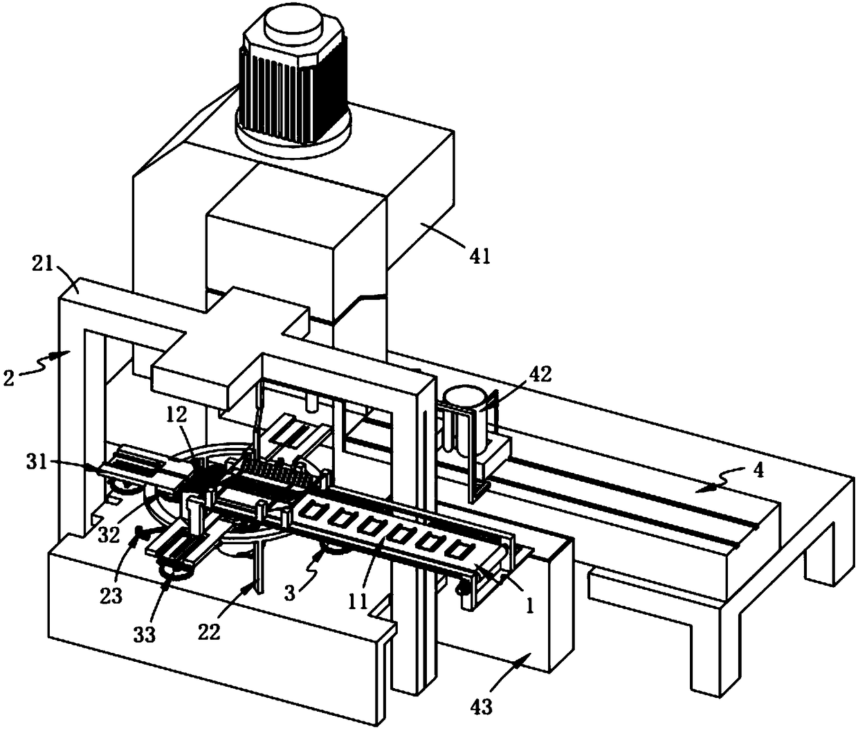
[0078] like figure 1 As shown, the fully automatic assembly system for electromagnetic clutch coils for compressors includes:

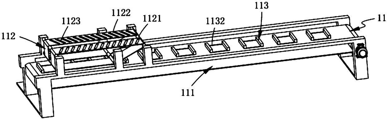
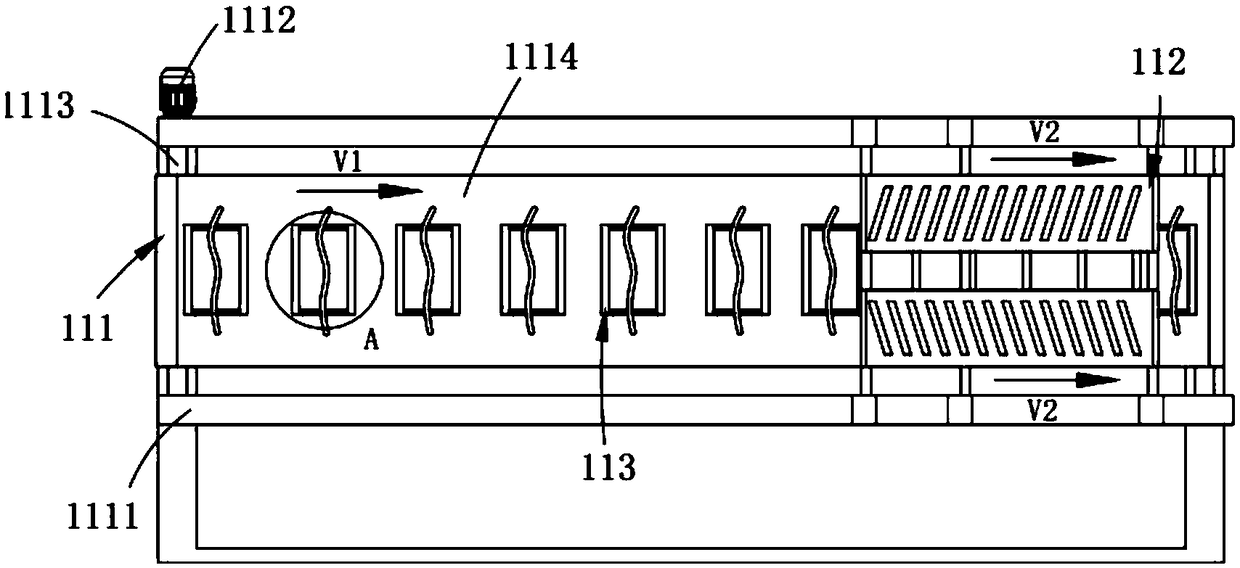
[0079] A first-level flattening mechanism 1, the first-level flattening mechanism 1 includes a straightening assembly 11 and an outlet assembly 12 located at the output end of the straightening assembly 11 and perpendicular to the transmission direction of the straightening assembly 11;

[0080] The epicyclic mechanism 2, the epicyclic mechanism 2 includes a frame 21 for installing the straightening assembly 11, a switching assembly 22 arranged on the frame 21 and located below the straightening assembly 11 and installed on the The drive mechanism 23 on the frame 21;

[0081] The two-level flattening mechanism 3, the two-level flattening mechanism 3 is arranged in several groups on the switching assembly 22, which includes a receiving assembly 31 installed on the switching assembly 22, a sliding set under the receiving assembly 31 The first tighteni...

Embodiment 2

[0131] like Figure 11 , Figure 12 and Figure 13 As shown, the components that are the same as or corresponding to those in the first embodiment are marked with the corresponding reference numerals in the first embodiment. For the sake of simplicity, only the differences from the first embodiment will be described below. The difference between this embodiment two and embodiment one is:

[0132] further, such as Figure 11 and Figure 12 As shown, the coil upper assembly 42 includes:

[0133] The supporting member 421, the supporting member 421 includes a frame platform 4211 arranged on one side of the crimping machine 41 and set on the same level as the workbench of the crimping machine 41, set on the frame platform 4211 and Two sets of slide rails 4212 and a feeding bucket 4213 fixedly arranged on the vehicle frame platform 4211 and provided with a gap between the upper surface of the vehicle frame platform 4211 are arranged along the width direction of the vehicle fra...


PUM


Abstract

The invention relates to an electromagnetic clutch coil automatic assembly system for a compressor. The system comprises a first level flattening mechanism, a turnover mechanism, a secondary level flattening mechanism and a wiring mechanism, and the first level flattening mechanism comprises a compressing straightening assembly and a wire outlet assembly at an output end of the compressing straightening assembly; the turnover mechanism comprises a frame for mounting the compressing straightening assembly, switching assemblies disposed on the frame and a driving mechanism mounted on the frame;the second level flattening mechanism circumferentially displaying on the plurality of groups of switching assemblies includes a receiving assembly mounted on the switching assemblies, a first bandingassembly arranged slidably below the receiving assembly and a second banding assembly located behind the first banding assembly, and the first banding assembly and the second banding assembly are both in cooperative drive with the drive mechanism; the wiring mechanism includes a pressure wire machine, a coil upper assembly and a reset assembly; the system solves the technical problem that a wireis twisted and pinched when the wire works, and a wire head cannot be accurately placed under the pressure wire machine every time under the automatic conveying.

Description

technical field [0001] The invention relates to the technical field of inductance coil materials, in particular to a fully automatic assembly system for an electromagnetic clutch coil for a compressor. Background technique [0002] In general, an electromagnetic clutch field coil assembly for a compressor is an electric device that generates a magnetic field by electromagnetic induction of an electromagnetic coil when energized, and causes the disk of the hub engaged with the drive shaft of the compressor to be attracted to the belt by magnetic force. The friction surface side of the wheel is in dynamic connection with this surface to transmit the driving force of the pulley rotated by the engine to the disc of the hub which engages the drive shaft of the compressor. . [0003] Patent No. CN101438074B discloses an electromagnetic clutch field coil assembly for compressors, and more specifically relates to such an electromagnetic clutch field coil assembly for compressors, w...

Claims


Application Information

Patent Timeline
Patent Type & Authority Applications(China)
IPC IPC(8): H01F41/04
CPCH01F41/04
Inventor 沈生贤
Owner 赵娟
Why Eureka
Try Eureka