
antenna

An antenna and power feeding technology, which is applied in the direction of antenna, antenna coupling, antenna components, etc., can solve the problems of poor isolation and achieve the effect of transmitting and receiving isolation, less spectrum resources, and real-time transmission and reception

Active Publication Date: 2021-11-02
HUNAN MAXWELL ELECTRONICS TECH
View PDF7 Cites 0 Cited by
  • Summary
  • Abstract
  • Description
  • Claims
  • Application Information

AI Technical Summary

Problems solved by technology

[0004] The main purpose of the present invention is to provide an antenna, aiming to solve the problem of poor isolation when the small antenna used for low-power ultra-wideband radio ranging in the prior art transmits and receives in real time at the same frequency

Method used


Image

  • antenna
  • antenna
  • antenna

Examples


Embodiment Construction

[0027] The following will clearly and completely describe the technical solutions in the embodiments of the present invention with reference to the accompanying drawings in the embodiments of the present invention. Obviously, the described embodiments are only part of the embodiments of the present invention, not all of them. Based on the embodiments of the present invention, all other embodiments obtained by persons of ordinary skill in the art without creative efforts fall within the protection scope of the present invention.

[0028] It should be noted that all directional indications (such as up, down, left, right, front, back...) in the embodiments of the present invention are only used to explain the relationship between the components in a certain posture (as shown in the accompanying drawings). Relative positional relationship, movement conditions, etc., if the specific posture changes, the directional indication will also change accordingly.

[0029] In addition, in t...


PUM


Abstract

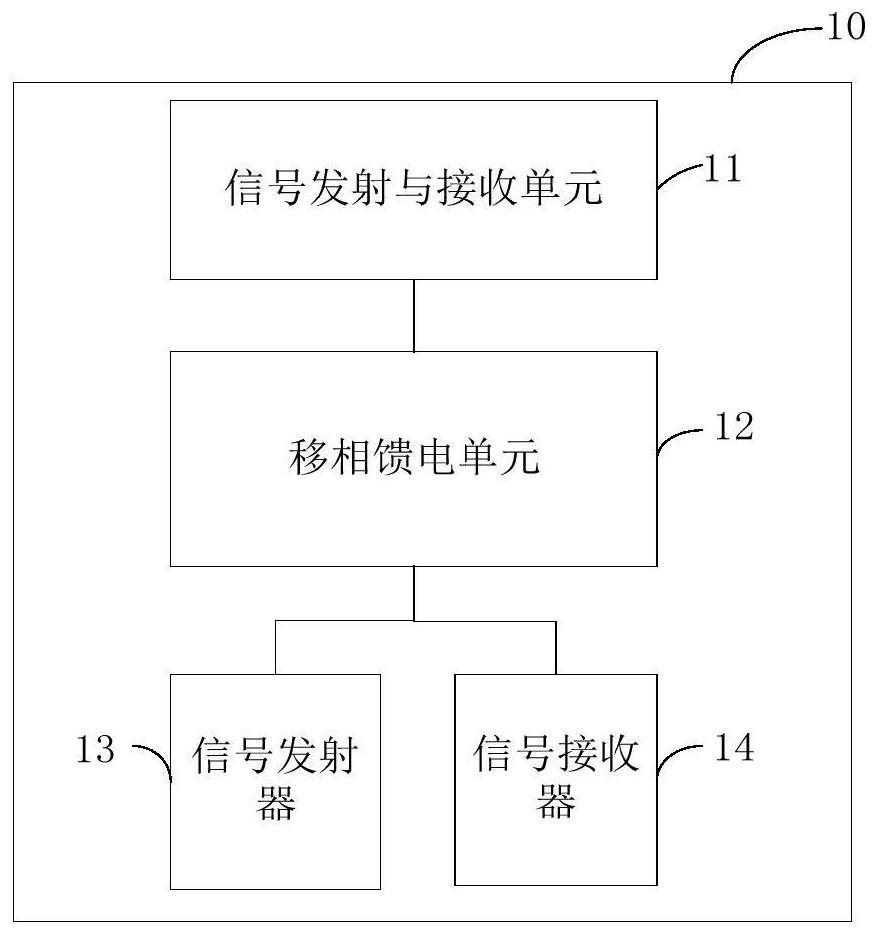
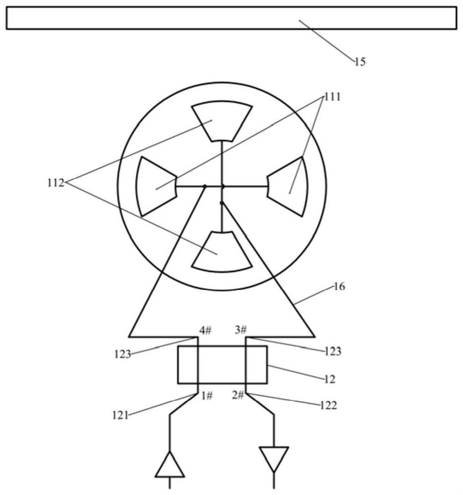
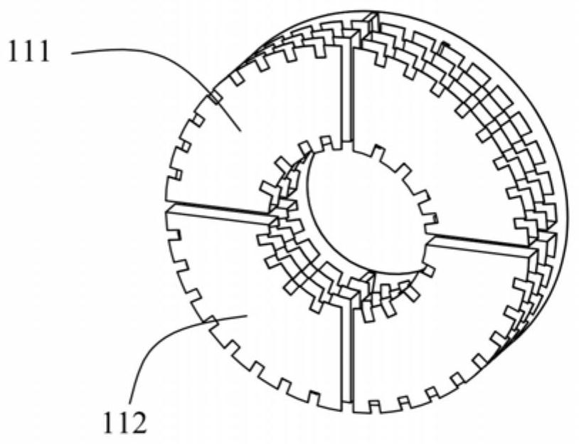
The invention provides an antenna, including a signal transmitting and receiving unit, a phase-shifting feed unit, a signal transmitter and a signal receiver, the signal transmitting and receiving unit includes two vertically arranged radiation groups, and the phase-shifting feeding unit includes a signal The transmitting port, the signal receiving port and multiple connection ports, the transmitting signal of the signal transmitter passes through the phase-shifting feed unit to generate two transmitting signals with a phase difference of 90°, which are respectively sent to two radiation groups for radiation synthesis Transmit circularly polarized waves; the two radiation groups are also used to receive circularly polarized waves that are opposite to the direction of the transmitted circularly polarized waves, and induce one induction signal respectively, and the phase difference between the two induction signals The angle is 90°, and the two induction signals are synthesized into the receiving signal at the signal receiving port after being acted on by the phase-shifting feed unit. The antenna of the present invention can still realize real-time transmission and reception when transmitting and receiving at the same frequency, and can reduce frequency occupation of bandwidth, so that the antenna occupies less spectrum resources.

Description

technical field [0001] The invention relates to the technical field of radio ranging, in particular to an antenna. Background technique [0002] In low-power ultra-wideband radio ranging equipment, it is generally required that the antenna can transmit and receive radio signals at the same time. The radio signal received by the receiving antenna includes the self-interference signal emitted by itself and the reflected signal of the distant target. The strength of the self-transmitted signal is often much greater than the reflected signal, which may burn out the receiver's low-noise amplifier and other electronic circuits. Therefore, it is necessary to minimize the receiving antenna from receiving the self-transmitted signal. In addition, in order to improve the detection distance and the signal-to-noise ratio of the echo signal, it is also necessary to reduce the strength of the self-interference signal. Both of the above two requirements need to improve the transceiver is...

Claims


Application Information

Patent Timeline
Patent Type & Authority Patents(China)
IPC IPC(8): H01Q1/52H01Q1/50H01Q1/38
CPCH01Q1/38H01Q1/50H01Q1/525
Inventor 张传胜陈莉岳并蒂穆雪峰刘健李武刚
Owner HUNAN MAXWELL ELECTRONICS TECH
Learn More