Device and method for detecting cervical spine activity

A detection device and detection method technology, applied in diagnostic recording/measurement, medical science, diagnosis, etc., can solve problems such as long measurement time, large amount of calculation, complex pose calculation algorithm, etc., to achieve fast and accurate measurement methods, avoid The effect of resisting the mind and reducing the burden on the neck

Inactive Publication Date: 2020-08-25
SHANDONG UNIV
View PDF11 Cites 0 Cited by
  • Summary
  • Abstract
  • Description
  • Claims
  • Application Information

AI Technical Summary

Problems solved by technology

[0003] The inclinometer usually measures the average angular offset between the end point and the starting point in an activity cycle, the measurement accuracy is low, and the rotation activity cannot be effectively measured
The cervical spine activity measuring instrument combines an inclinometer and a compass to measure the cervical spine activity. Although it has good accuracy and reliability, the structure is complex and the measurement process is cumbersome, which increases the resistance of the testees.
[0004] The photographic analysis method is easy to operate and has high measurement accuracy. However, it is necessary to attach easily identifiable marks on the body surface of the test subject before the measurement, which will cause discomfort to the test subject. Generally, multiple cameras are required to collect data, and the pose calculation algorithm is complex, and the calculation is difficult. large
CT 3D reconstruction has good resolution and high measurement accuracy, but the measurement time is long, the calculation is complicated, and the radioactivity is large
Tape measurement and visual inspection methods are simple, but rely on the experience of the measurer, the measurement accuracy is low, the efficiency is low, and the measurer's work intensity is high

Method used


Image

  • Device and method for detecting cervical spine activity
  • Device and method for detecting cervical spine activity
  • Device and method for detecting cervical spine activity

Examples


Embodiment Construction

[0045] It should be pointed out that the following detailed description is exemplary and intended to provide further explanation to the present application. Unless defined otherwise, all technical and scientific terms used herein have the same meaning as commonly understood by one of ordinary skill in the art to which this application belongs.

[0046] It should be noted that the terminology used here is only for describing specific implementations, and is not intended to limit the exemplary implementations according to the present application. As used herein, unless the context clearly dictates otherwise, the singular is intended to include the plural, and it should also be understood that when the terms "comprising" and / or "comprising" are used in this specification, they mean There are features, steps, operations, means, components and / or combinations thereof.

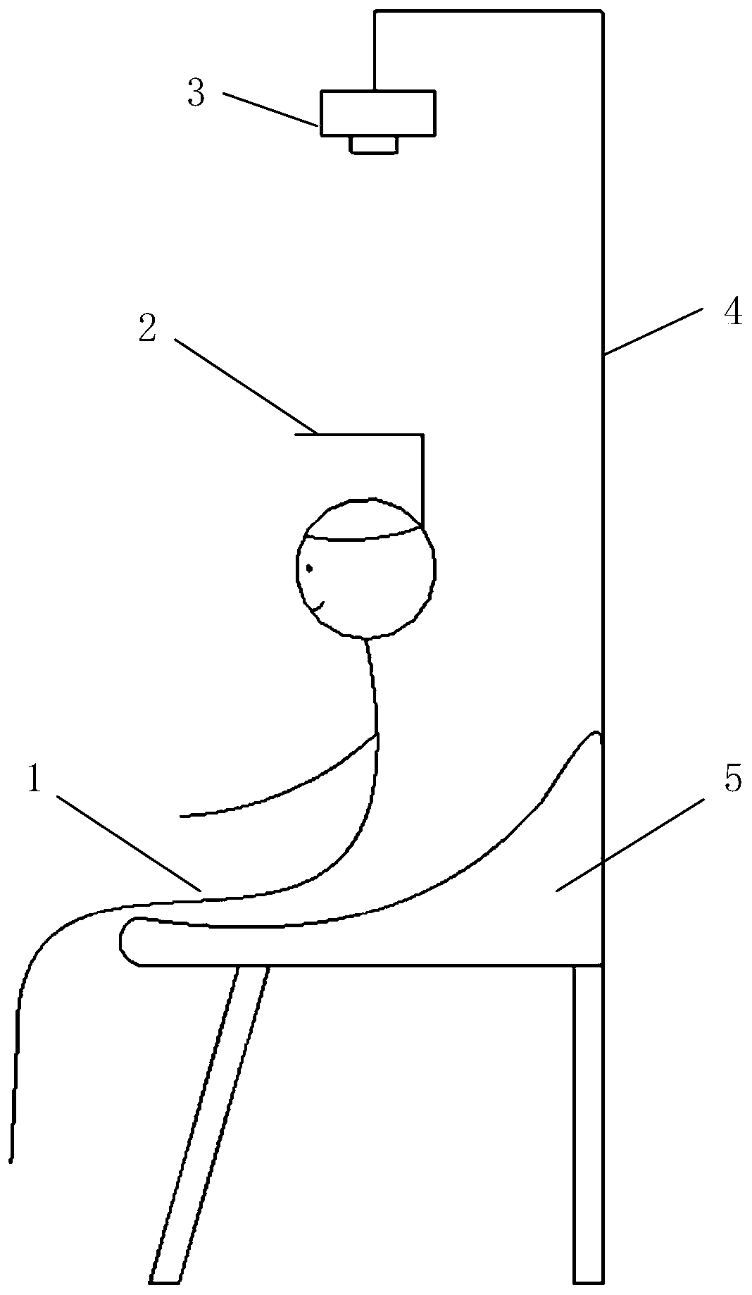
[0047] In a typical implementation example of the present application, such as figure 1 As shown, a cervical sp...


PUM


Abstract

The invention discloses a cervical motion detecting device and method. The device comprises a marking headband, a signal acquisition device and a microprocessor, the marking headband comprises a marking plate, the center of the marking plate is marked with two vertical marking lines, and one of which is long and the other one is short; the signal acquisition device collects the gray scale information and the depth information of black mark lines on the marking plate in real time, and transmits the collected image information to a microprocessor; the microprocessor analyzes the image and measures the length of the mark lines, the gray scale information and the depth information to calculate cervical motion information. The device has the advantages of simple structure, convenient installation and low cost, and a marking device is light and easy to wear, which can effectively reduce the neck burden of a tested person, and avoid the resistance of a test subject to a measuring instrument.The measuring method is fast, accurate and easy to implement, and can effectively reduce the testing time.

Description

technical field [0001] The present disclosure relates to the technical fields of machine vision and medical equipment, in particular to a device and method for detecting the range of motion of the cervical spine. Background technique [0002] At present, the inventor has found in the research that the current situation and existing problems of the detection of cervical spine activity are: the existing technology of cervical spine activity measurement is inclinometer measurement, cervical spine activity measuring instrument, photographic analysis, CT three-dimensional reconstruction measurement, tape measure , visual inspection. [0003] The inclinometer usually measures the average angular offset between the end point and the starting point in an activity cycle, the measurement accuracy is low, and the rotation activity cannot be effectively measured. The cervical spine mobility measuring instrument combines an inclinometer and a compass to measure the cervical spine mobili...

Claims


Application Information

Patent Timeline
Patent Type & Authority Patents(China)
IPC IPC(8): A61B5/11
CPCA61B5/1118A61B5/1127
Inventor 蒋奇魏国招
Owner SHANDONG UNIV
Why Eureka
Try Eureka