
Colloid hydraulic compression molding device and method of performing compression molding on plate by utilizing colloid hydraulic compression molding device

A hydraulic mold and colloid technology, applied in the direction of forming tools, metal processing equipment, manufacturing tools, etc., can solve the problems of non-compliance with production efficiency, increase the process steps of replacing molds, and high mold costs, and achieve low design change costs, flexible design, and high cost. Product quality effect

Pending Publication Date: 2019-02-22
福建振丰矿物新材料有限公司
View PDF9 Cites 0 Cited by
  • Summary
  • Abstract
  • Description
  • Claims
  • Application Information

AI Technical Summary

Problems solved by technology

The basic workbench of the traditional press to produce metal sheets is a three-piece set of the lower mold embedded with the lower surface of the mold, the mold, and the upper mold embedded with the upper surface of the mold. This not only increases the process steps of mold replacement, but also increases the mold cost. , does not meet the high production efficiency of today's era

Method used


Image

  • Colloid hydraulic compression molding device and method of performing compression molding on plate by utilizing colloid hydraulic compression molding device

Examples


Embodiment Construction

[0021] The technical solutions in the embodiments of the present invention will be clearly and completely described below. Obviously, the described embodiments are only some of the embodiments of the present invention, but not all of them. Based on the embodiments of the present invention, all other embodiments obtained by persons of ordinary skill in the art without making creative efforts belong to the protection scope of the present invention.

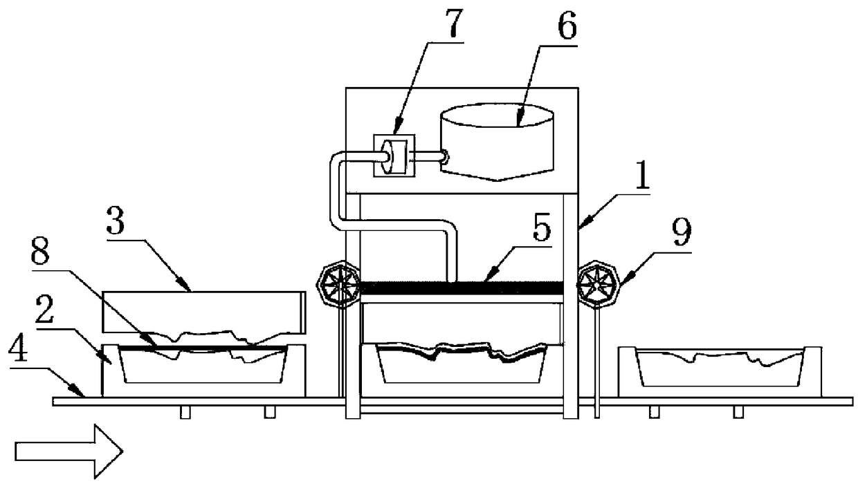
[0022] Such as figure 1 As shown, a colloid hydraulic molding device includes a base 1, a rigid lower mold 2, a colloid upper mold 3, and a mobile workbench 4 installed under the base 1, and a rubber diaphragm 5 is installed under the base 1, And located above the mobile workbench 4; a hydraulic oil reservoir 6 and a hydraulic valve 7 are installed on the base 1; the hydraulic oil reservoir 6 and the hydraulic valve 7 communicate with each other by means of a pressure medium inlet, and the pressure medium The entrance extends to th...


PUM


Abstract

The invention provides a colloid hydraulic compression molding device and a method of performing compression molding on a plate by utilizing the colloid hydraulic compression molding device; a flexible colloid upper die having a certain deformation degree is made of a colloid, and is combined with a rigid lower die, and by utilizing a method of hydraulic push molding, processing efficiency is increased while die casting cost is reduced. The colloid hydraulic compression molding device comprises a base, the rigid lower die, the colloid upper die and a moving working platform arranged below thebase; a rubber diaphragm is arranged below the base, and is located above the moving working platform; the base is provided with a hydraulic oil storage device and a hydraulic valve; the rigid lower die is placed on the moving working platform; the colloid upper die is placed above the rigid lower die; a plate to be compression molded can be placed between the colloid upper die and the rigid lowerdie; and the rigid lower die and the colloid upper die can move into the base by means of the moving working platform and is located under the rubber diaphragm.

Description

technical field [0001] The invention relates to a compression molding device and its use method, in particular to a colloid hydraulic compression molding device and a method for molding a plate using the same. Background technique [0002] With the progress of the times, heavy industry is also developing rapidly with the support of the state. As one of the most widely used formed metal sheets, it is particularly important to save costs and improve production efficiency when it is used in large quantities. [0003] At present, the production of most of the commercial vehicles, automobiles, heavy trucks, construction machinery, motor vehicles, building coverings and other formed metal sheets is realized by traditional hydraulic presses. The basic workbench of the traditional press to produce metal sheets is a three-piece set of the lower mold embedded with the lower surface of the mold, the mold, and the upper mold embedded with the upper surface of the mold. This not only inc...

Claims


Application Information

Patent Timeline
Patent Type & Authority Applications(China)
IPC IPC(8): B21D13/02B21D37/01
CPCB21D13/02B21D37/01
Inventor 何轸炎谢进义林庚申
Owner 福建振丰矿物新材料有限公司
Learn More