
Welding device of cable assembly

A welding device and cable assembly technology, applied in auxiliary devices, welding equipment, auxiliary welding equipment, etc., can solve problems affecting the transmission of radio frequency signals by connectors and cable assemblies, affecting the transmission of radio frequency signals by products, and inaccurate placement of connectors, etc. , to achieve high quality, high stability of welding quality and good welding effect

Pending Publication Date: 2019-02-22
SHANGHAI RADIALL ELECTRONICS
View PDF10 Cites 3 Cited by
  • Summary
  • Abstract
  • Description
  • Claims
  • Application Information

AI Technical Summary

Problems solved by technology

[0004] 1) Manually place the connector at the welding position in the coil, which is prone to inaccurate placement of the connector, which in turn tends to cause uneven heating of the terminals, resulting in uneven flow of solder after melting, which ultimately affects the use of connectors and cable assemblies The ability to transmit radio frequency signals
[0005] 2) During the heating process, the insulation medium of the cable is heated and expanded, causing the cable insulation layer to expand and move back, thereby creating a gap between the terminal end and the shielding layer of the cable, and affecting the transmission of radio frequency signals by the product

Method used


Image

  • Welding device of cable assembly
  • Welding device of cable assembly
  • Welding device of cable assembly

Examples


Embodiment Construction

[0035] The implementation of the present invention will be illustrated by specific specific examples below, and those skilled in the art can easily understand other advantages and effects of the present invention from the contents disclosed in this specification.

[0036] It should be noted that the structures, proportions, sizes, etc. shown in the drawings of this specification are only used to match the content disclosed in the specification, for those who are familiar with this technology to understand and read, and are not used to limit the conditions for the implementation of the present invention , so it has no technical substantive meaning, and any modification of structure, change of proportional relationship or adjustment of size shall still fall within the scope of the disclosure of the present invention without affecting the functions and objectives of the present invention. within the range covered by the technical content. At the same time, terms such as "upper", ...


PUM


Abstract

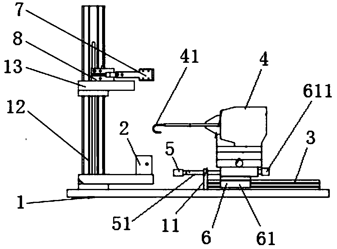
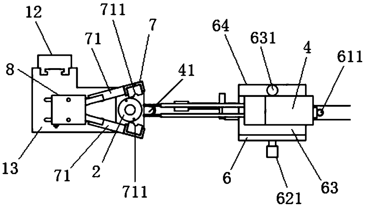
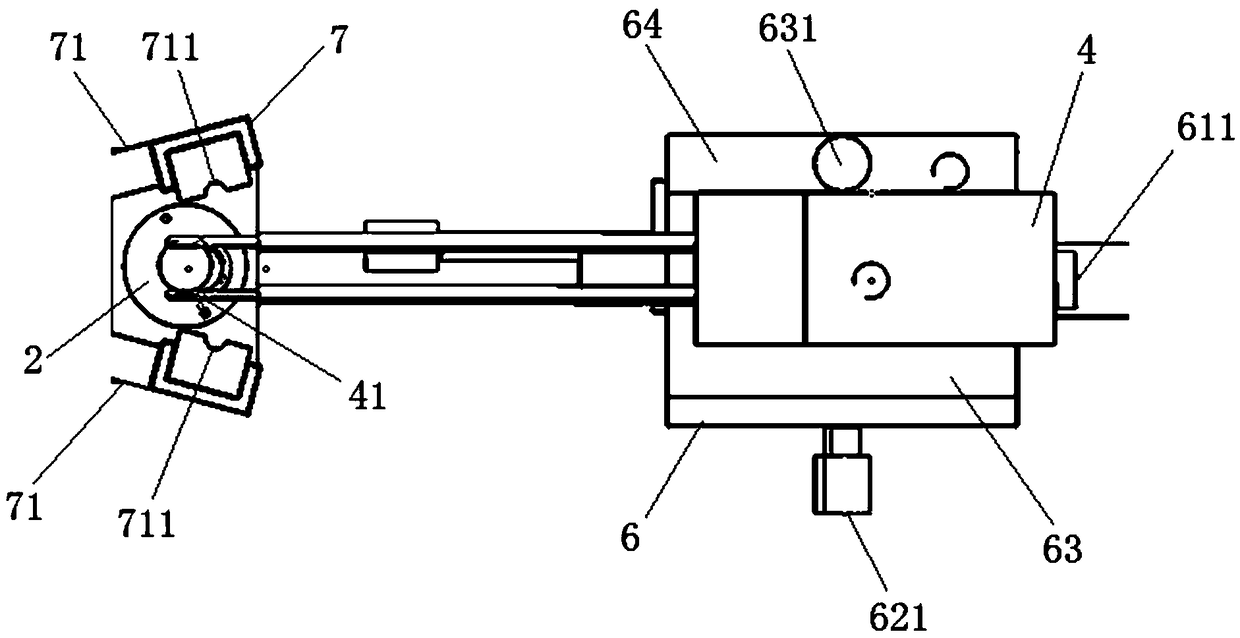
The invention provides a welding device of a cable assembly. The welding device comprises a bottom plate, a connector positioning seat mounted on the bottom plate, a sliding rail mounted on the bottomplate, a welding machine mounted on the bottom plate, and a limiting part mounted on the bottom plate. The connector positioning seat is provided with a positioning groove, the welding machine is provided with an induction coil, the welding machine can move along the welding machine in the direction of being close to and away from the connector positioning seat, and the limiting part is used forlimiting the movement route of the welding machine in the direction of being close to the connector positioning seat. According to the welding device of the cable assembly, a connecting device and thewelding machine are positioned through the connector positioning seat and the limiting part, thus, it can be guaranteed that a terminal of the connecting device is accurately located at the set position in the induction coil, and it is guaranteed that the welding quality and the welding percent of pass of the welding device of the cable assembly are higher.

Description

technical field [0001] The invention relates to a welding device, in particular to a welding device for a cable assembly. Background technique [0002] In the prior art, the whole process of welding the connector and the cable is manually operated and controlled; the specific process is as follows: first, hold the cable in one hand, and put the connector in the induction coil for heating with the other hand, until the tin wire is completely melted and Heating is stopped after flowing, so that the terminal of the connector and the cable are welded together, thereby obtaining the cable assembly, and finally the cable assembly is taken out. [0003] The above-mentioned method of manually welding the connector and the cable has the following defects: [0004] 1) Manually place the connector at the welding position in the coil, which is prone to inaccurate placement of the connector, which in turn tends to cause uneven heating of the terminals, resulting in uneven flow of solder...

Claims


Application Information

Patent Timeline
Patent Type & Authority Applications(China)
IPC IPC(8): B23K3/00B23K3/08B23K37/04B23K1/002B23K101/38
CPCB23K1/002B23K3/00B23K3/08B23K3/085B23K3/087
Inventor 宫友婕
Owner SHANGHAI RADIALL ELECTRONICS
Learn More