
Self-protection shaft locking protection device for bearing grinder grinding shaft

A bearing grinding machine and protection device technology, applied in the direction of grinding drive device, grinding/polishing safety device, grinding machine, etc., can solve the problems of oil viscosity drop, wrench injury to staff, grinding wheel spindle fracture and damage, etc.

Inactive Publication Date: 2019-02-22
彭雪雅
View PDF0 Cites 2 Cited by
  • Summary
  • Abstract
  • Description
  • Claims
  • Application Information

AI Technical Summary

Problems solved by technology

[0003] 1. When the grinding wheel used for bearing grinding is installed on the transmission box, the existing method is to fix the main shaft of the grinding wheel, and turn the locking teeth inside the transmission box with a wrench, so that the locking teeth can fix the main shaft of the grinding wheel. After fixing After the grinding wheel is fixed, the staff forget to load and unload the wrench, so that the wrench is still stuck at the position of the locking shaft, causing the rotation of the transmission box to drive the rotation of the grinding wheel spindle, causing the wrench to be thrown by the grinding wheel spindle and injuring the staff
[0004] 2. At the same time, during the rotation of the existing grinding wheel spindle, a large amount of powder chips are produced due to the continuous grinding of the grinding wheel on the bearing, and some tiny powder chips enter the inside of the grinding wheel spindle, and are produced by the continuous friction between the grinding wheel spindle and tiny iron filings. Heat, the temperature of the grinding wheel spindle rises to 60 degrees Celsius and continues to work, resulting in a decrease in the viscosity of the oil and a decrease in the steel of the grinding wheel spindle, resulting in fracture and damage to the grinding wheel spindle

Method used


Image

  • Self-protection shaft locking protection device for bearing grinder grinding shaft
  • Self-protection shaft locking protection device for bearing grinder grinding shaft
  • Self-protection shaft locking protection device for bearing grinder grinding shaft

Examples


Embodiment

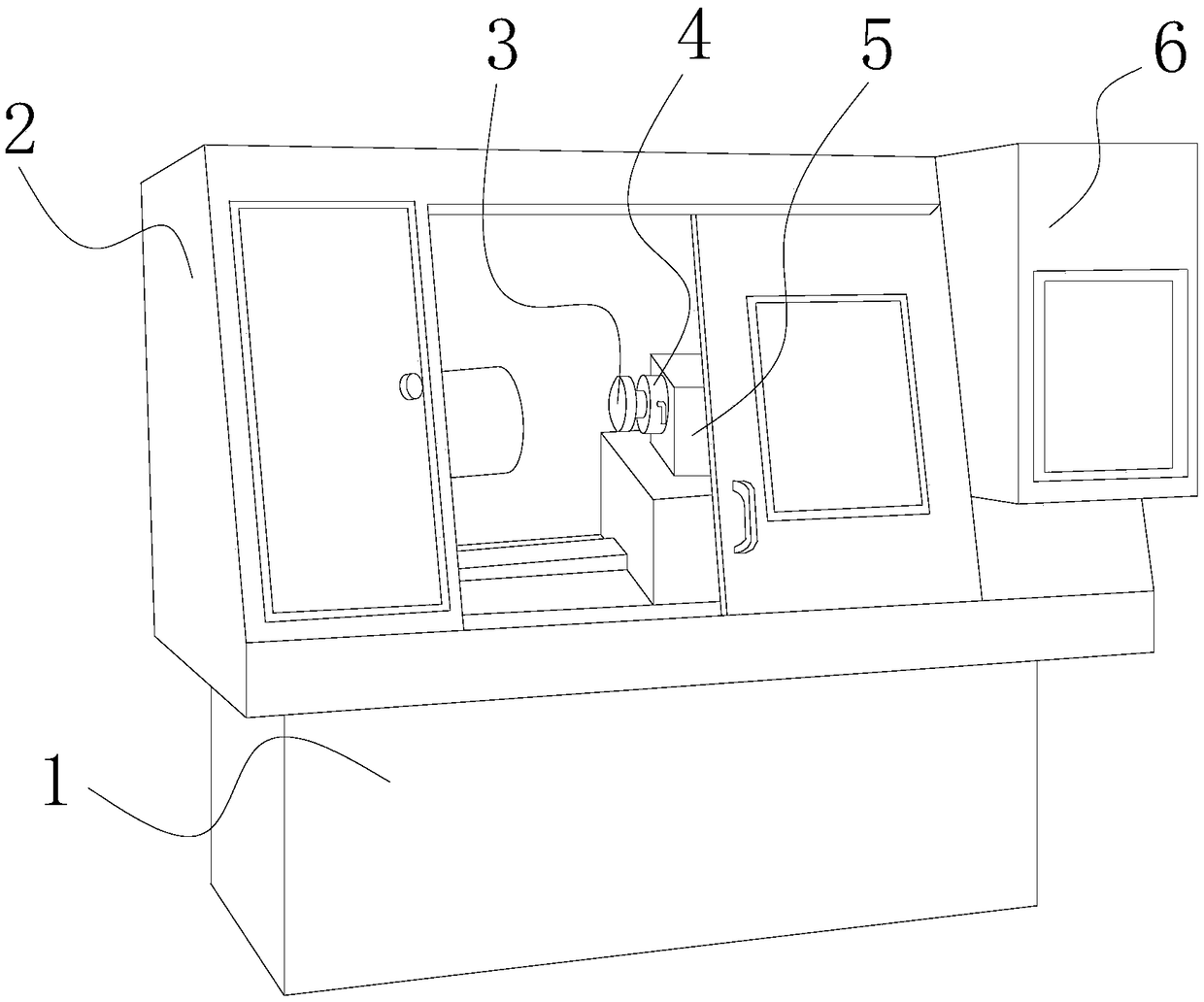
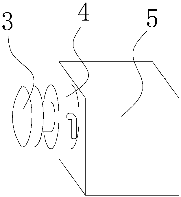
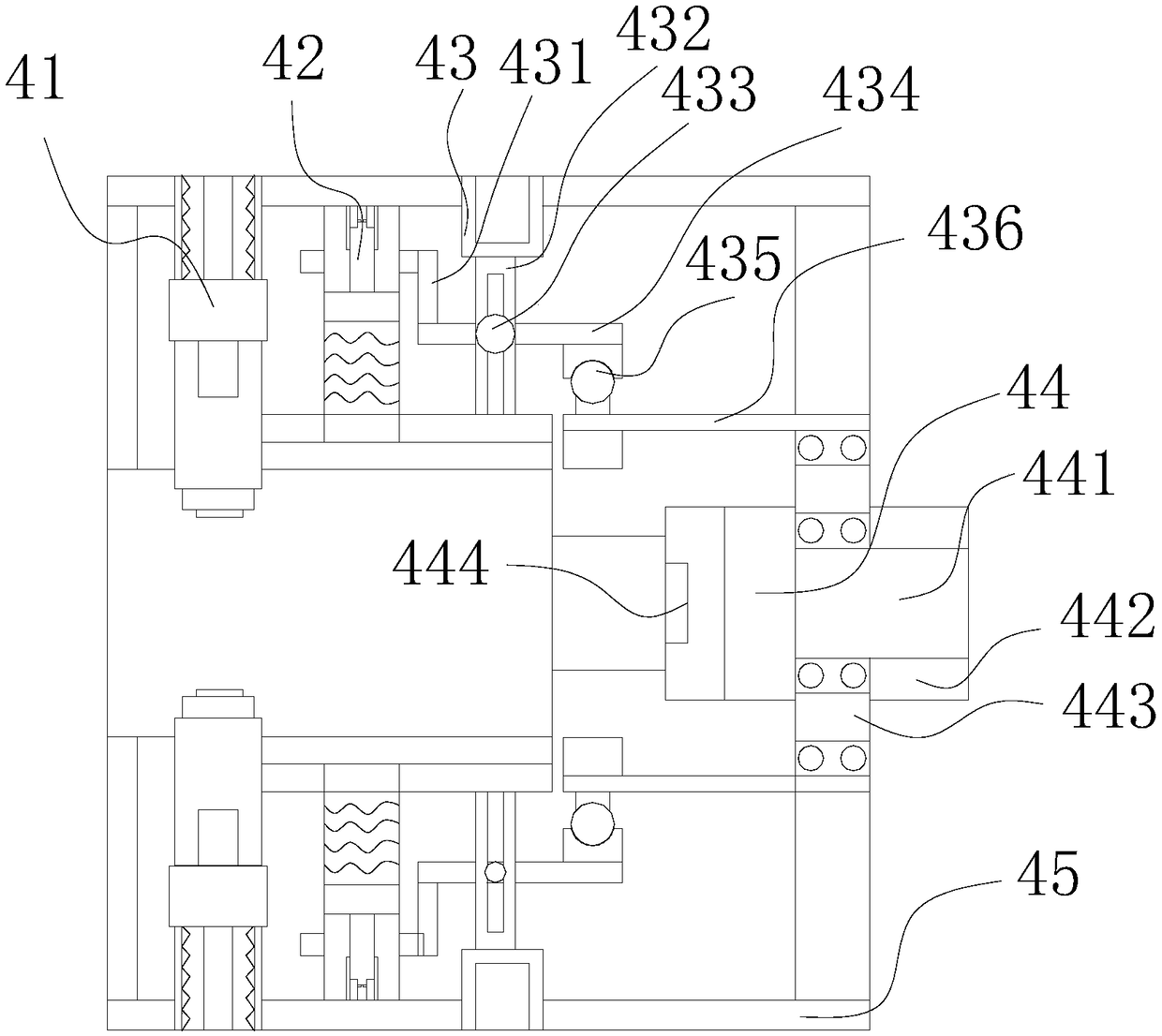
[0030] Such as Figure 1-Figure 9 As shown, the present invention provides a self-protection lock shaft protection device for a bearing grinder sand shaft, the structure of which includes a base 1, an operating cabinet 2, a grinding wheel 3, a fly shaft protection device 4, a transmission box 5, and a control box 6. The base 1 is horizontally installed on the lower surface of the operating cabinet 2, the grinding wheel 3 is connected to the fly shaft protection device 4 through the grinding wheel shaft, and the axes where the two are located are located on the same horizontal line, and the fly shaft protection device 4 It is horizontally embedded and installed inside the transmission box 5 and is mechanically transmitted through the shaft. The control box 6 is horizontally installed on the front surface of the operation cabinet 2. The knock-up shaft protection device 4 includes an anti-knock-up mechanism 41, a linkage transmission mechanism 42, a transmission mechanism 43, an ...


PUM


Abstract

The invention discloses a self-protection shaft locking protection device for a bearing grinder grinding shaft. The self-protection shaft locking protection device structurally comprises a base, an operation case, a grinding wheel, a hitting flying shaft protection device, a transmission case and a control box. The base is horizontally installed on the lower surface of the operation case. The grinding wheel is in shaft connection with the hitting flying shaft protection device through a grinding wheel shaft, and the axes of the grinding wheel and the hitting flying shaft protection device arelocated on the same horizontal line. The hitting flying shaft protection device is horizontally embedded and installed in the transmission case, and mechanical transmission is conducted through a shaft. Through the self-protection shaft locking protection device, the problems that a worker forgets to detach a wrench, thus the wrench is still clamped to the position of a locking shaft rod, consequently the transmission case rotates to drive a grinding wheel spindle to rotate, the wrench is thrown away by the grinding wheel spindle to hit and injure the worker, the grinding wheel spindle continues working after temperature is increased to 60 DEG C, oil viscosity is lowered, rigidity of the grinding wheel spindle is lowered, and the grinding wheel spindle is broken and damaged are prevented effectively.

Description

technical field [0001] The invention relates to the field of bearing protection, in particular to a self-protecting and locking shaft protection device for a grinding shaft of a bearing grinding machine. Background technique [0002] The bearing grinding machine is used for grinding and finishing the inner wall and outer wall of the bearing, grinding away the iron thorns on the outer surface of the bearing, and preventing the production of bearings from having multiple corner thorns, but the existing bearing grinding machines have the following problems: [0003] 1. When the grinding wheel used for bearing grinding is installed on the transmission box, the existing method is to fix the main shaft of the grinding wheel, and turn the locking teeth inside the transmission box with a wrench, so that the locking teeth can fix the main shaft of the grinding wheel. After fixing After the grinding wheel is fixed, the staff forgets to load and unload the wrench, so that the wrench is...

Claims


Application Information

Patent Timeline
IPC IPC(8): B24B9/04B24B55/00B24B41/04B24B47/12
CPCB24B9/04B24B41/04B24B47/12B24B55/00
Inventor 彭雪雅
Owner 彭雪雅
Learn More