Transfer printing machine

A technology of transfer printing machine and reducer, which is applied in the direction of rotary printing machine, printing machine, transfer printing, etc. It can solve the problems of difficult control of the speed of the track pulley, long warm-up time when starting up, affecting transfer efficiency, etc., and achieves saving transfer. Reduce printing time, reduce labor burden, and improve transfer efficiency

Active Publication Date: 2019-02-22
湖北永和安门业有限公司
View PDF10 Cites 4 Cited by
  • Summary
  • Abstract
  • Description
  • Claims
  • Application Information

AI Technical Summary

Problems solved by technology

[0005] The existing transfer printing machine can only transfer one sheet at a time, which has low efficiency and long warm-up time when starting up;
[0006] In the existing transfer printing machine, when the vacuum chamber is transferred through the rail, the rail stroke is short, and the speed of the rail pulley is too fast to be controlled, and the vacuum chamber is opened or closed by electric to realize automation, which has high cost and low safety performance;
[0007] In the existing transfer printing machine, the furnace door of the heating furnace needs to be opened by the thrust when the vacuum chamber enters, which affects the transfer efficiency;
[0008] In the existing transfer printing machine, the vacuum chamber needs to be opened before the material required for transfer enters, and the seal needs to be closed after entering, and then a vacuum environment is created, and the vacuum chamber is opened or closed by electric to realize automation, high cost and low safety performance

Method used


Image

  • Transfer printing machine
  • Transfer printing machine
  • Transfer printing machine

Examples


Embodiment 1

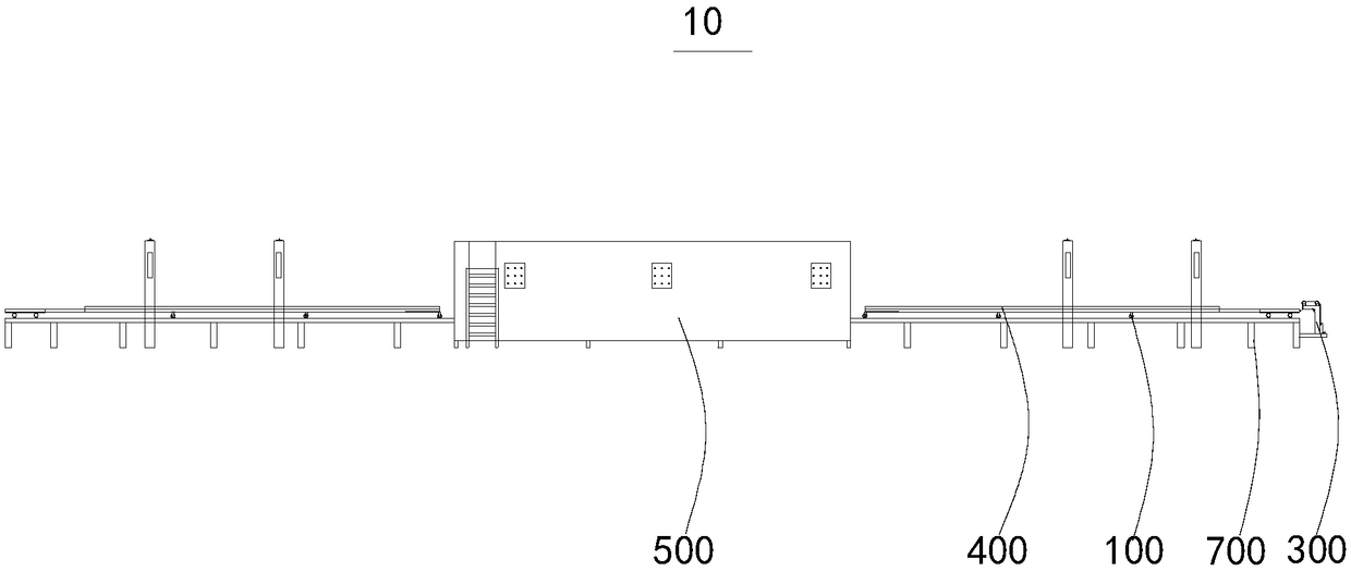
[0071] figure 1 Provide the first structural schematic diagram of the transfer machine 10 for the embodiment of the present invention, specifically show the overall schematic diagram of the transfer machine 10;

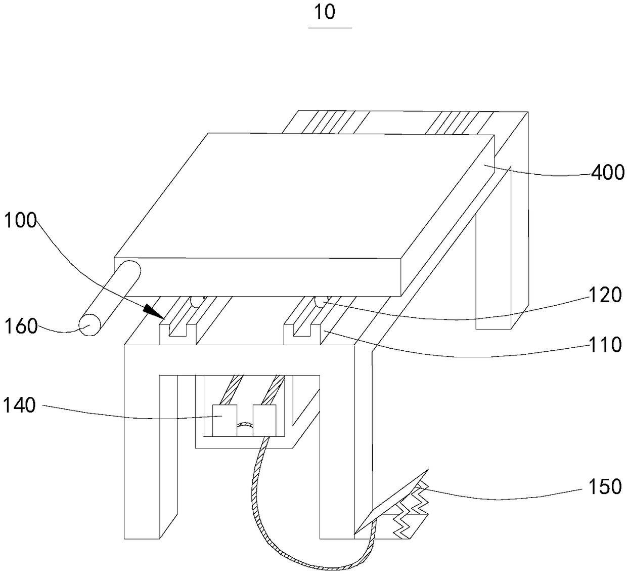
[0072] figure 2 A second structural schematic diagram of the transfer machine 10 is provided for the embodiment of the present invention, specifically showing a schematic diagram of the transfer machine track group 100 and other parts included in the transfer machine 10;

[0073] image 3 for figure 2 A schematic diagram of the structure of a perspective;

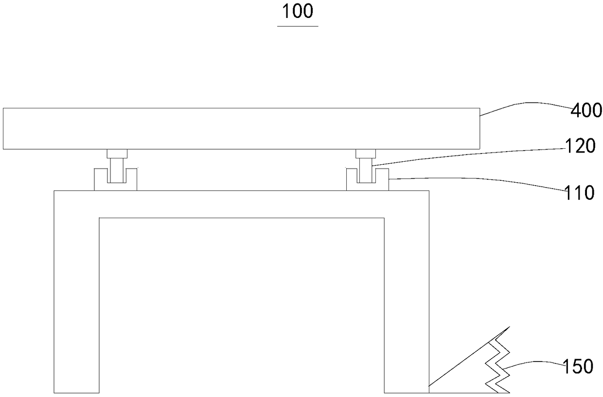
[0074] Figure 4 Provide the first structural schematic diagram of the transfer machine track set 100 for the embodiment of the present invention, specifically showing the connection relationship between the track part 110 and the pulley part 120;

[0075] Figure 5 Provide a schematic structural diagram of the heating furnace door opening and closing group 200 for the embodiment of the present invention, s...

Embodiment 2

[0126] Figure 9 A second structural schematic diagram of the track set 100 of the transfer machine is provided for the embodiment of the present invention, specifically showing a structural schematic view of different arrangements of the pulley fixing parts 130 in the track set 100 of the transfer machine.

[0127] Please refer to Figure 1 to Figure 3 ,Please refer to Figure 5 to Figure 9 , a transfer machine 10 is provided for this embodiment of the present invention. from figure 1 and Figure 5 It can be seen that a transfer machine 10 includes a transfer machine track group 100 , a heating furnace door opening and closing group 200 , a vacuum chamber opening and closing group 300 and a vacuum chamber 400 .

[0128] This embodiment provides a transfer printing machine 10, which is substantially the same as the transfer printing machine 10 of the first embodiment, the difference between the two lies in the arrangement of the track part 110 and the pulley fixing part 13...

Embodiment 3

[0134] Figure 10 A second structural schematic diagram of the vacuum chamber opening and closing group 300 is provided for the embodiment of the present invention. , specifically showing a structural schematic view of the vacuum chamber opening and closing group 300 using the belt 360 .

[0135] Please refer to Figure 1 to Figure 7 ,Please refer to Figure 10 , a transfer machine 10 is provided for this embodiment of the present invention. from figure 1 and Figure 5 It can be seen that a transfer machine 10 includes a transfer machine track group 100 , a heating furnace door opening and closing group 200 , a vacuum chamber opening and closing group 300 and a vacuum chamber 400 .

[0136] This embodiment provides a transfer machine 10 which is substantially the same as the transfer machine 10 of the first embodiment, the difference between the two lies in the connection between the pneumatic part 320 and the first matching part 330 .

[0137] Please refer to Figure 1...


PUM


Abstract

The invention discloses a transfer printing machine. The transfer printing machine comprises transfer printing rail sets, heating furnace door opening and closing sets, a vacuum cavity opening and closing set and vacuum cavities. Each transfer printing rail set comprises rail portions, roller portions, roller fixing portions and reduction boxes. The transfer printing rail sets are used for transferring the vacuum cavities to a transfer printing box. The roller portions are arranged on the corresponding rail portions in a sliding mode. Each heating furnace door opening and closing set comprisesa time schedule control portion and an opening and closing portion, wherein the opening and closing portion is connected with a heating furnace door. The vacuum cavity opening and closing set comprises an opening portion, a pneumatic portion and a first matching portion, wherein the opening portion is connected with the pneumatic portion, and the pneumatic portion is connected with the first matching portion. The controllability of actions of the rails and the vacuum cavity transfer speed are achieved through the reduction boxes, the time schedule control portions control the heating furnacedoors, the opening and closing portions provide power, artificial burden is reduced, opening and closing of vacuum cavity doors are controlled manually, manual control is convenient and fast, the safety performance is high, pneumatic devices are adopted, saves energy and are efficient, the transfer printing machine can be used for performing transfer printing on profiled plates, and a plurality ofplates can be subjected to transfer printing simultaneously.

Description

technical field [0001] The invention relates to the field of transfer printing machines, in particular to a transfer printing machine. Background technique [0002] The transfer printing machine is the general term for the machines used in the transfer printing technology, mainly by heating the pigment molecules into the medium. The colors are vivid and layered, and can show the subtle color difference between adjacent details; the special ribbon contains a unique protective film, which can achieve continuous color gradation. [0003] The inventor finds in research that existing transfer printing machines have the following disadvantages at least: [0004] The existing transfer printing machines all transfer printing to flat plates; [0005] The existing transfer printing machine can only transfer one sheet at a time, which has low efficiency and long warm-up time when starting up; [0006] In the existing transfer printing machine, when the vacuum chamber is transferred ...

Claims


Application Information

Patent Timeline
Patent Type & Authority Applications(China)
IPC IPC(8): B41F16/00
CPCB41F16/00B41F16/0046B41F16/0093
Inventor 李春来李祥红
Owner 湖北永和安门业有限公司
Why Eureka
Try Eureka