Exciting beam for pavement breaking vehicle

A vibration excitation beam and vibration excitation technology, applied in roads, roads, road repair and other directions, can solve the problems of difficulty in reaching the crushing depth and crushing quality, high energy consumption, low efficiency, etc., to reduce vibration impact, reduce micro-deformation, The effect of reducing the effect of strength

Pending Publication Date: 2019-02-22
YICHANG JIANGXIA MARINE MACHINERY
View PDF1 Cites 13 Cited by
  • Summary
  • Abstract
  • Description
  • Claims
  • Application Information

AI Technical Summary

Problems solved by technology

[0002] At present, the equipment used for crushing cement pavement includes single-hammer type, door-knife type and multi-hammer type equipment for crushing. When crushing, it will exert a strong impact on the ground, make noise, and it is difficult to meet the requirements of crushing depth and crushing quality. High energy consumption and low efficiency

Method used


Image

  • Exciting beam for pavement breaking vehicle
  • Exciting beam for pavement breaking vehicle
  • Exciting beam for pavement breaking vehicle

Examples


Embodiment 1

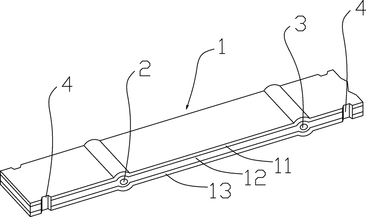
[0034] Such as figure 1 Among them, an excitation beam for a road crushing vehicle, the excitation beam 1 is composed of a plurality of excitation layers stacked from top to bottom, and each excitation layer is fixedly connected by a hoop 7 . With this structure, it is possible to reduce the amount of deformation of the upper surface and the lower surface of each excitation layer, reduce the heat generated by the alternating stress, and reduce the influence on the strength.

Embodiment 2

[0036] On the basis of Example 1, the preferred scheme is as figure 2 Among them, a first support hole 2 and a second support hole 3 are respectively provided at positions close to both ends of the exciting beam 1;

[0037] The first support hole 2 and the second support hole 3 are located between two excitation layers, and each excitation layer is provided with an arc structure corresponding to the support holes. With this structure, it is possible to reduce the difficulty of post-processing and facilitate the adoption of cold forging technology, especially the influence of the processing of the first support hole 2 and the second support hole 3 on the material. For example, due to the reduction of machining, steel materials with high elasticity can be selected for each excitation layer, such as silicon-manganese spring steel doped with one or more of boron, niobium or molybdenum.

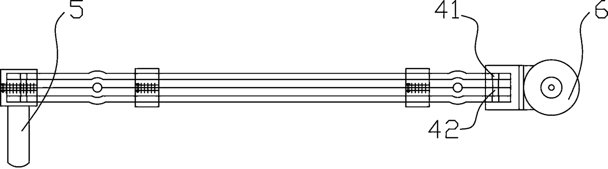
[0038] The preferred solution is as figure 2 Among them, an excitation hammer 5 is provide...

Embodiment 3

[0042] On the basis of Example 1, the preferred scheme is as figure 2 Among them, a first support hole 2 and a second support hole 3 are respectively provided at positions close to both ends of the exciting beam 1;

[0043] The first support hole 2 and the second support hole 3 are located in the excitation layer of the middle layer, and each excitation layer is provided with an arc structure corresponding to the support hole.

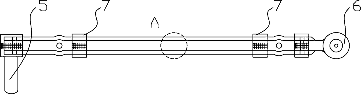
[0044] In a preferred solution, an exciting hammer 5 is provided at one end of the exciting beam 1, and a mounting seat for installing the exciting motor 6 is provided at the other end, and the exciting hammer 5 is connected with the exciting beam 1 through a hoop structure, and the The two sides of the hoop structure are connected by multiple bolts;

[0045] The mounting base is fixedly connected to the excitation layer on the middle layer;

[0046] The positions of the hoop 7 on both sides are connected by a plurality of bolts. With this structur...


PUM


Abstract

The invention provides an exciting beam for a pavement breaking vehicle, and relates to the field of cement pavement breaking equipment. The exciting beam consists of eight exciting layers which are stacked from top to bottom, wherein the exciting layers are fixedly connected through hoops; the positions, close to the two ends, of the exciting beam are separately equipped with a first supporting hole and a second supporting hole; the first supporting hole and the second supporting hole are positioned between the two exciting layers; and each exciting layer is equipped with an arc-shaped structure which corresponds to the supporting holes. Or the first supporting hole and the second supporting hole are positioned on the exciting layer on the middle layer, and each exciting layer is equippedwith the arc-shaped structure which corresponds to the supporting holes. A multi-layer structure design is adopted, so that micro deformation amplitude of each exciting layer can be reduced, and therefore, strength influences caused by alternating stress are reduced.

Description

technical field [0001] The invention relates to the field of cement pavement crushing equipment, in particular to an exciting beam for a pavement crushing vehicle. Background technique [0002] At present, the equipment used for crushing cement pavement includes single-hammer type, door-knife type and multi-hammer type equipment for crushing. When crushing, it will exert a strong impact on the ground, make noise, and it is difficult to meet the requirements of crushing depth and crushing quality. High energy consumption and low efficiency. Chinese patent document CN206052519U describes a cement concrete pavement resonance crusher, which crushes the pavement by adopting a resonance mode, with low noise and high efficiency. The cement concrete pavement is crushed by this vibration excitation method, and the part transmitting the excitation vibration is the excitation beam. Under the condition of alternating stress, the position of the largest deformation in the middle of the ...

Claims


Application Information

Patent Timeline
Patent Type & Authority Applications(China)
IPC IPC(8): E01C23/12
CPCE01C23/124
Inventor 何明黑保江姜归鹤黄恋弓文达刘志东王军杨波胡三宝田哲文韩爱国彭晶
Owner YICHANG JIANGXIA MARINE MACHINERY
Why Eureka
Try Eureka