Wind power blade main beam or subsidiary beam structure and fabrication method thereof

A wind power blade and manufacturing method technology, applied in the wind power blade main beam or auxiliary beam structure and the field of manufacturing, can solve the problems of large difference in resin content, prone to quality defects, low resin content, etc., to improve the bonding performance, increase the Length and number of corners, good quality results

Inactive Publication Date: 2019-02-22
ZHUZHOU TIMES NEW MATERIALS TECH
View PDF5 Cites 13 Cited by
  • Summary
  • Abstract
  • Description
  • Claims
  • Application Information

AI Technical Summary

Problems solved by technology

In this patent, rectangular sheets of different widths are used, and the molten resin in the lower layer tends to permeate to the upper layer excessively, resulting in a low interlayer resin content in the lower layer, and the resin content of interlayer prepregs varies greatly in different regions, which is prone to quality defects

Method used


Image

  • Wind power blade main beam or subsidiary beam structure and fabrication method thereof
  • Wind power blade main beam or subsidiary beam structure and fabrication method thereof
  • Wind power blade main beam or subsidiary beam structure and fabrication method thereof

Examples


Embodiment 1

[0063] 1) Clean the surface of the main beam or auxiliary beam mold, lay a release cloth on the main beam or auxiliary beam mold, lay a resin film on the release cloth, and lay a surface density of 100g / m above the resin film 2 Prepregs for glass fiber triaxial fabrics;

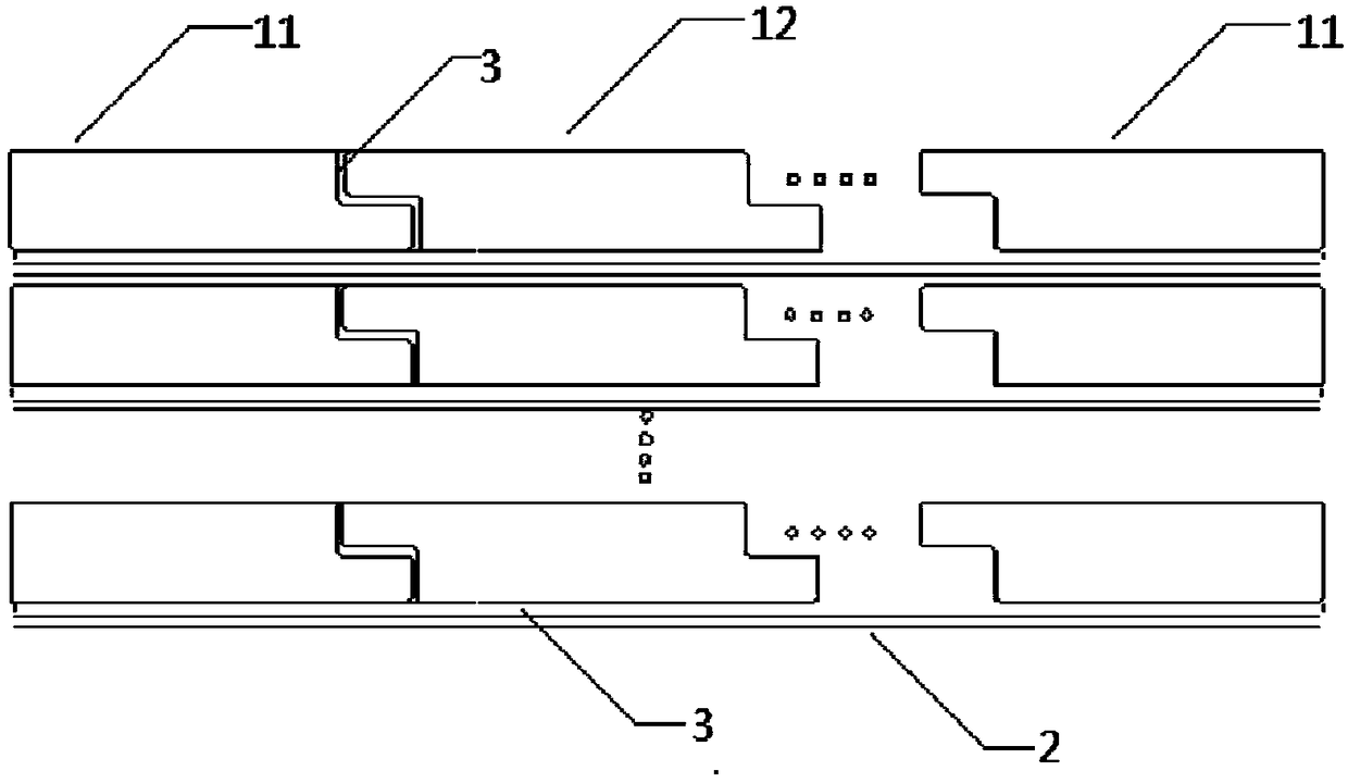
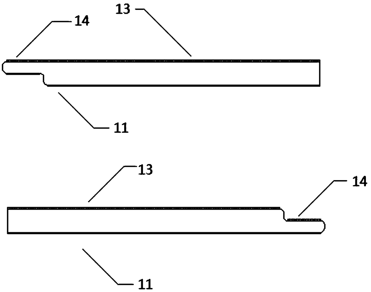
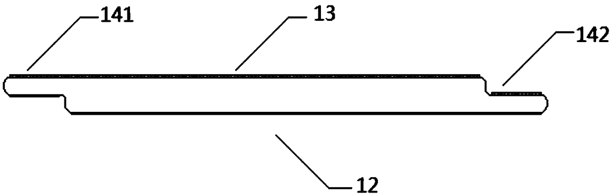
[0064] 2) Both the upper surface and the lower surface of the pultruded sheet are laid with release cloth, and the sheet without the release cloth is laid on the prepreg of the glass fiber triaxial fabric. It is closely attached to the facade of the main beam or auxiliary beam mold, and the superimposed part of the adjacent plates in the chord direction is superimposed between the side plates of the adjacent plates to form a Z-shaped channel;

[0065] 3) Lay multiple layers of resin film between adjacent layers of boards in the longitudinal direction, and the surface density of the laying above the resin film is 100g / m 2 Prepregs for glass fiber triaxial fabrics;

[0066] 4) Repeat steps 2) and 3), so that ...

Embodiment 2

[0069] 1) Clean the surface of the main beam or auxiliary beam mold, lay a release cloth on the main beam or auxiliary beam mold, and lay resin powder on the release cloth. The surface density of the laying surface above the resin powder is 300g / m 2 carbon fiber biaxial fabric;

[0070] 2) Both the upper surface and the lower surface of the pultruded sheet are laid with release cloth, and the sheet without the release cloth is laid on the carbon fiber biaxial fabric. The façade of the beam mold is solid, and the overlapping parts of the adjacent plates in the chord direction are superimposed between the side plates of the adjacent plates to form a Z-shaped channel;

[0071] 3) Lay multiple layers of resin film between adjacent layers of boards in the longitudinal direction, and the surface density of the laying above the resin film is 300g / m 2 carbon fiber biaxial fabric;

[0072] 4) Repeat steps 2) and 3), so that the laying is completed in a cycle, and the uppermost layer ...

Embodiment 3

[0075] 1) Clean the surface of the main beam or auxiliary beam mold, lay a release cloth on the main beam or auxiliary beam mold, and lay a resin film on the release cloth;

[0076] 2) Both the upper surface and the lower surface of the pultruded sheet are laid with release cloth, and the sheet with the release cloth removed is laid on the resin film. The facade is solid, and the overlapping parts of adjacent panels in the chord direction overlap each other through the side panels of adjacent panels to form a Z-shaped channel;

[0077] 3) laying a multi-layer resin film between adjacent layers of boards in the longitudinal direction;

[0078] 4) Repeat steps 2) and 3), so that the laying is completed in a cycle, and the uppermost layer is the board;

[0079] 5) Lay release cloth, VAP film, and vacuum film on the main beam or auxiliary beam mold that has been laid in step 4). The edge of the vacuum film is sealed with a sealing tape, and the vacuum device is connected through ...


PUM


Abstract

The invention discloses a wind power blade main beam or subsidiary beam structure. The wind power blade main beam or subsidiary beam structure comprises plate materials, low-surface-density fabric andresin, wherein the plate materials are superimposed in both the chord direction and the longitudinal direction and comprise main plates and side plates arranged at the end portions of the main plates, the thickness of the side plates is less than that of the main plates, the superimposed parts of the adjacent plate materials in the chord direction are superimposed through the side plates of the adjacent plate materials, and the thickness of the superimposed parts of the side plates is not more than that of the main plates, the low-surface-density fabric is arranged between the adjacent platematerials in the longitudinal direction, and the positions between the plate materials as well as the positions between the plate materials and the low-surface-density fabric are filled with the resin. By means of the plate materials and a fabrication method, the resin passage length and the number of corners are effectively increased, excessive penetration of the molten lower-layer resin towardsupper layers is prevented, the flowing speed of the resin can be effectively controlled, the situation that the interlamination resin content is low to cause defects is prevented, the use ratio of theresin is increased, and the quality of wind power blades obtained finally is good.

Description

technical field [0001] The invention belongs to the technical field of wind power blades, and in particular relates to a wind power blade main girder or auxiliary girder structure and a manufacturing method thereof. Background technique [0002] At present, the mainstream production process of large-scale wind power blades is the vacuum infusion process. The main principle is to build a vacuum system after the fiber cloth is completely laid, and infuse resin when a certain vacuum negative pressure is drawn. The resin enters the system quickly under the action of atmospheric pressure to complete the infusion of the blade. In the design of the infusion process, the number of the injection port of the infusion system and the suction port of the vacuum system is limited. At the same time, there will be tiny air bubbles entering the vacuum system with the resin during the mixing of the resin. In order to remove these impurities and ensure the quality of the infusion, the infusion...

Claims


Application Information

Patent Timeline
Patent Type & Authority Applications(China)
IPC IPC(8): F03D80/00B29C70/30B29C70/54B29L31/08
CPCB29C70/30B29C70/54B29L2031/082F03D80/00B29C70/304Y02E10/72
Inventor 梁自禄喻雄陈煌宋杨马倩倩
Owner ZHUZHOU TIMES NEW MATERIALS TECH
Why Eureka
Try Eureka