
Position control system of hydraulic stepping driver and control method applying same

A technology of a control system and a control method, which is applied in the directions of fluid pressure actuation system components, fluid pressure actuation devices, servo motor components, etc., can solve the problems of increasing cost, reducing system reliability, increasing additional cost, etc., and achieving position control High precision, strong anti-oil pollution ability, high degree of automation

Pending Publication Date: 2019-02-22
FUJIAN UNIV OF TECH
View PDF0 Cites 1 Cited by
  • Summary
  • Abstract
  • Description
  • Claims
  • Application Information

AI Technical Summary

Problems solved by technology

However, this type of technology has high cost (especially electro-hydraulic servo control), is sensitive to oil pollution and has low system efficiency
In addition, in order to achieve position control, high-precision external or built-in sensors are often required, which not only increases additional costs, but also makes installation inconvenient and reduces system reliability.
That is, the sensor will not only increase the cost and increase the risk of failure, but also affect the wiring, and the installation of the sensor is sometimes limited by the installation space

Method used


Image

  • Position control system of hydraulic stepping driver and control method applying same

Examples


Embodiment Construction

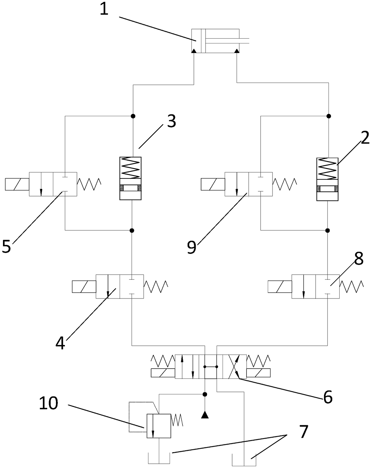
[0017] Such as figure 1 As shown, the position control system of the present invention includes a master cylinder 1, a first slave cylinder 3, a second slave cylinder 2, a first switching valve 4, a second switching valve 5, a third switching valve 8, and a fourth switching valve 9 and the three-position four-way valve 6, the inside of the first slave cylinder 3 and the second slave cylinder 2 are composed of a slave piston with a seal and a return spring, and one end of the three-position four-way valve 6 The two ports are respectively connected to the hydraulic source and the oil tank 7, and the safety relief valve 10 is connected between the hydraulic source and the three-position four-way valve 6, and the two-way port at the other end of the three-position four-way valve 6 is connected to the first switching valve 4, the second One end of the three switching valves 8 is connected, the other end of the first switching valve 4 is respectively connected with one end of the se...


PUM


Abstract

The invention discloses a position control system of a hydraulic stepping driver and a control method applying the same. The position control system comprises a main cylinder, a first driven cylinder,a second driven cylinder, a first switching valve, a second switching valve, a third switching valve, a fourth switching valve and a three-position four-way valve, wherein the interiors of the firstdriven cylinder and the second driven cylinder each are composed of a driven piston with a sealing piece and a reset spring, two through holes in one end of the three-position four-way valve are correspondingly connected with a hydraulic source and an oil tank, through holes in another two ends of the three-position four-way valve are correspondingly connected with the other end of the first switching valve and the other end of the third switching valve, the other end of the first switching valve is correspondingly connected with one end of the second switching valve and a spring-free cavity of the first driven cylinder, the other end of the second switching valve and a spring cavity of the first driven cylinder are connected in parallel and then are connected with a rodless cavity of themain cylinder, a rod cavity of the main cylinder is connected to one end of the fourth switching valve and a spring cavity of the second driven cylinder, and the other end of the fourth switching valve is connected with a spring-free cavity of the driven cylinder in parallel and then is connected with one end of the third switching valve. According to the position control system of the hydraulic stepping driver and the control method applying the same, accurate hydraulic cylinder stepping motion can be realized without a position sensor, and the system is low in cost and has strong oil-pollution resistance.

Description

technical field [0001] The invention relates to the field of hydraulic technology, in particular to a position control system of a hydraulic stepping driver and a control method thereof. Background technique [0002] In the case of high power, high responsiveness of position control, and compact structure, electro-hydraulic proportional control or electro-hydraulic servo control technology is generally used. However, this type of technology has high cost (especially electro-hydraulic servo control), is sensitive to oil contamination and has low system efficiency. In addition, in order to achieve position control, high-precision external or built-in sensors are often required, which not only increases additional costs, but also makes installation inconvenient and reduces system reliability. That is, the sensor will not only increase the cost and increase the risk of failure, but also affect the wiring, and the installation of the sensor is sometimes limited by the installati...

Claims


Application Information

Patent Timeline
IPC IPC(8): F15B21/00F15B13/02
CPCF15B13/02F15B21/00
Inventor 张树忠黄豪杰张兰刘喜涛李苏练国富唐一文晏岱陈丙三
Owner FUJIAN UNIV OF TECH
Learn More