
Forged isolation type vacuum starting valve

An isolation type, start-up valve technology, used in control valves, lift valves, valve details, etc., can solve problems such as false closing, unstable flow, valve damage, etc., to ensure sealing, eliminate customs clearance problems, and slow down the effect of the medium flow rate.

Pending Publication Date: 2019-02-22
MINGZHU VALVE GRP
View PDF0 Cites 0 Cited by
  • Summary
  • Abstract
  • Description
  • Claims
  • Application Information

AI Technical Summary

Problems solved by technology

[0003] When the medium is running in the pipeline, it is inevitable that there will be gas brought in. When the gas reaches a certain amount, it will seriously affect the flow capacity of the pipeline. This requires an exhaust valve to discharge the air in the pipeline; however, ordinary exhaust valves have One disadvantage: it is easy to contact with the atmosphere, which may affect the water quality, etc.; after the exhaust of the pipeline is completed, the exhaust valve is closed, and the gas in the pipeline may overflow due to the influence of the ambient temperature, but the liquid level does not change. The valve is still in the closed state, which causes the pressure difference between the inner cavity pressure of the exhaust valve and the atmospheric pressure to increase continuously, which causes excessive extrusion of the sealing surface, which is easy to damage the sealing surface, and may also cause damage to the entire valve due to the increase in the inner cavity pressure.
[0004] In addition, when the medium in the pipeline is transported, there will generally be some flow instability, so that the spool of some special valves will be impacted by the water flow, which will cause false closing.

Method used


Image

  • Forged isolation type vacuum starting valve
  • Forged isolation type vacuum starting valve
  • Forged isolation type vacuum starting valve

Examples


Embodiment Construction

[0027] The present invention will be further described below in conjunction with the accompanying drawings, and embodiments of the present invention will be given.

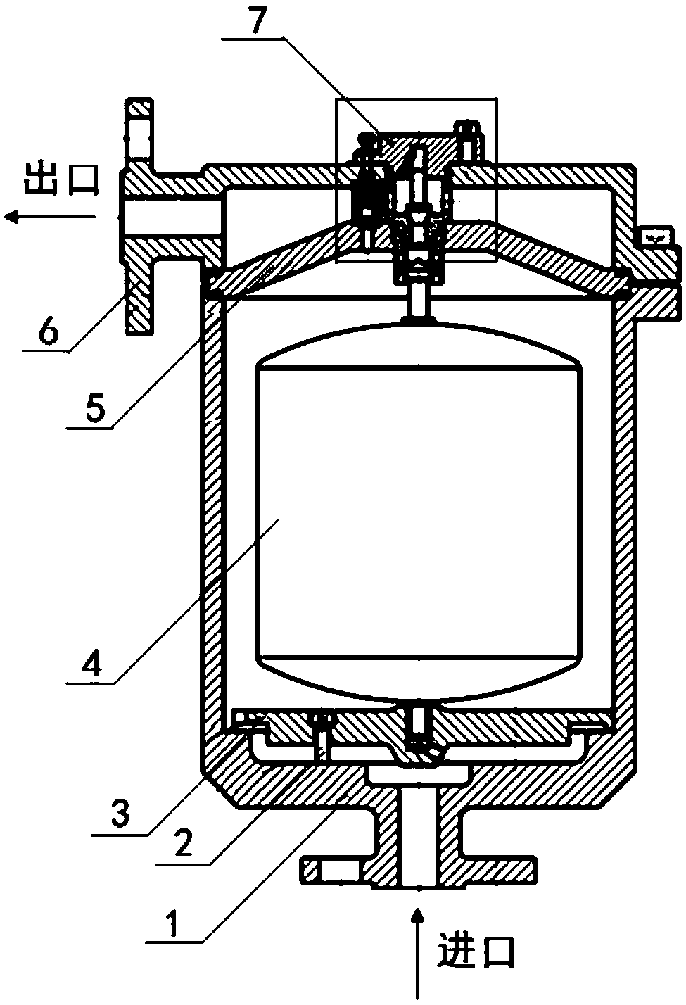
[0028] Such as figure 1 The isolated vacuum starting valve shown includes a valve body 1, a valve cover 6, an end cover 7, a buoy 4, and a valve seat. The body cavity is divided into an upper valve cavity A and a lower valve cavity B. The buoy 4 is placed in the lower valve cavity B directly connected with the water inlet, and the valve seat on the upper part of the buoy 4 is formed with the partition 5 and the water outlet. The connected valve body closing or opening mechanism; characterized in that:

[0029] The bottom of the lower valve cavity B in the water inlet of the valve body 1 is provided with an anti-scour structure to prevent the water flow from directly impacting the buoy;

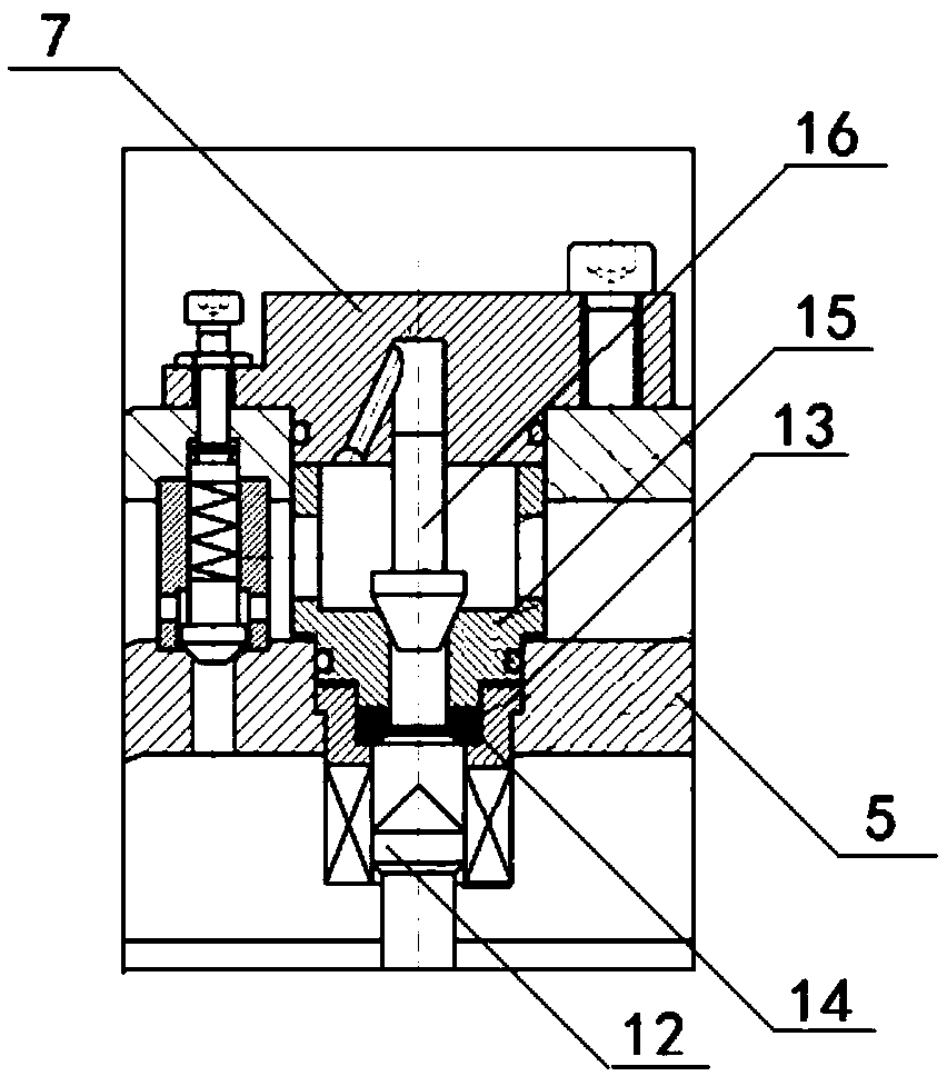
[0030] figure 2 The setting position and structural diagram of the anti-shock plate 3 in the valve body are given. The anti-...


PUM


Abstract

The invention provides a forged isolation type vacuum starting valve which comprises a valve body, a valve cover, an end cover, a floating cylinder and a valve base. An impact preventing structure forpreventing water flow from impacting the floating valve is arranged on the bottom of a lower valve cavity in a water inlet of the valve body. The valve base is an isolation type valve base mechanism.The isolation type valve base mechanism is composed of the valve base arranged on the partition plate, a floating cylinder guide inner ring arranged on the lower portion of the valve base, and a sealing ring arranged on the floating cylinder guide inner ring. An adjusting valve clack operating back and forth from bottom to top forms a lower portion closing or opening mechanism between the lower valve cavity and an upper valve cavity of the valve body. Meanwhile, a check valve clack arranged on the end cover forms a closing or opening mechanism between the lower valve cavity and the upper valve cavity of the valve body and a water outlet of the valve body. A pressure adjusting and relieving mechanism composed of the adjusting valve clack, an adjusting guide part, a spring, an adjusting piston and an adjusting screw is arranged between the partition plate and the end cover.

Description

technical field [0001] The invention relates to a starting valve, in particular to a forged isolation type vacuum starting valve. Background technique [0002] Isolation-type vacuum starting valve is a valve linked with a vacuum pump; it is suitable for when the pressure of the pipeline and pressure vessel is lower than atmospheric pressure, there is compressed gas formation, which affects the flow capacity of the pipeline and the auxiliary function of the safety of the pressure vessel. Valve body; once the exhaust is required, the vacuum start valve is opened, and the gas in the pipeline or pressure vessel is pneumatically drawn out by the vacuum pump, so as to ensure the safe operation of the pressurized pipeline. [0003] When the medium is running in the pipeline, it is inevitable that there will be gas brought in. When the gas reaches a certain amount, it will seriously affect the flow capacity of the pipeline. This requires an exhaust valve to discharge the air in the ...

Claims


Application Information

Patent Timeline
Patent Type & Authority Applications(China)
IPC IPC(8): F16K1/42F16K1/46F16K15/18F16K17/04F16K17/06F16K47/02
CPCF16K1/42F16K1/465F16K15/18F16K17/048F16K17/06F16K47/023
Inventor 杨伟刘帅胡赛芳
Owner MINGZHU VALVE GRP
Learn More