Imbibition and extraction device and imbibition and extraction experimental method

A technology of extraction device and experimental method, applied in measurement device, permeability/surface area analysis, suspension and porous material analysis, etc., can solve the problems of wall hanging, imbibition extraction process cannot be directly observed

Active Publication Date: 2019-02-22
CHINA UNIV OF PETROLEUM (BEIJING)
View PDF15 Cites 9 Cited by
  • Summary
  • Abstract
  • Description
  • Claims
  • Application Information

AI Technical Summary

Problems solved by technology

[0006] The purpose of the present invention is to provide a kind of imbibtion extraction device in order to overcome the problem that the imbibition oil hangs on the wall and the imbibition extraction process cannot be ...

Method used


Image

  • Imbibition and extraction device and imbibition and extraction experimental method
  • Imbibition and extraction device and imbibition and extraction experimental method
  • Imbibition and extraction device and imbibition and extraction experimental method

Examples


Embodiment 1

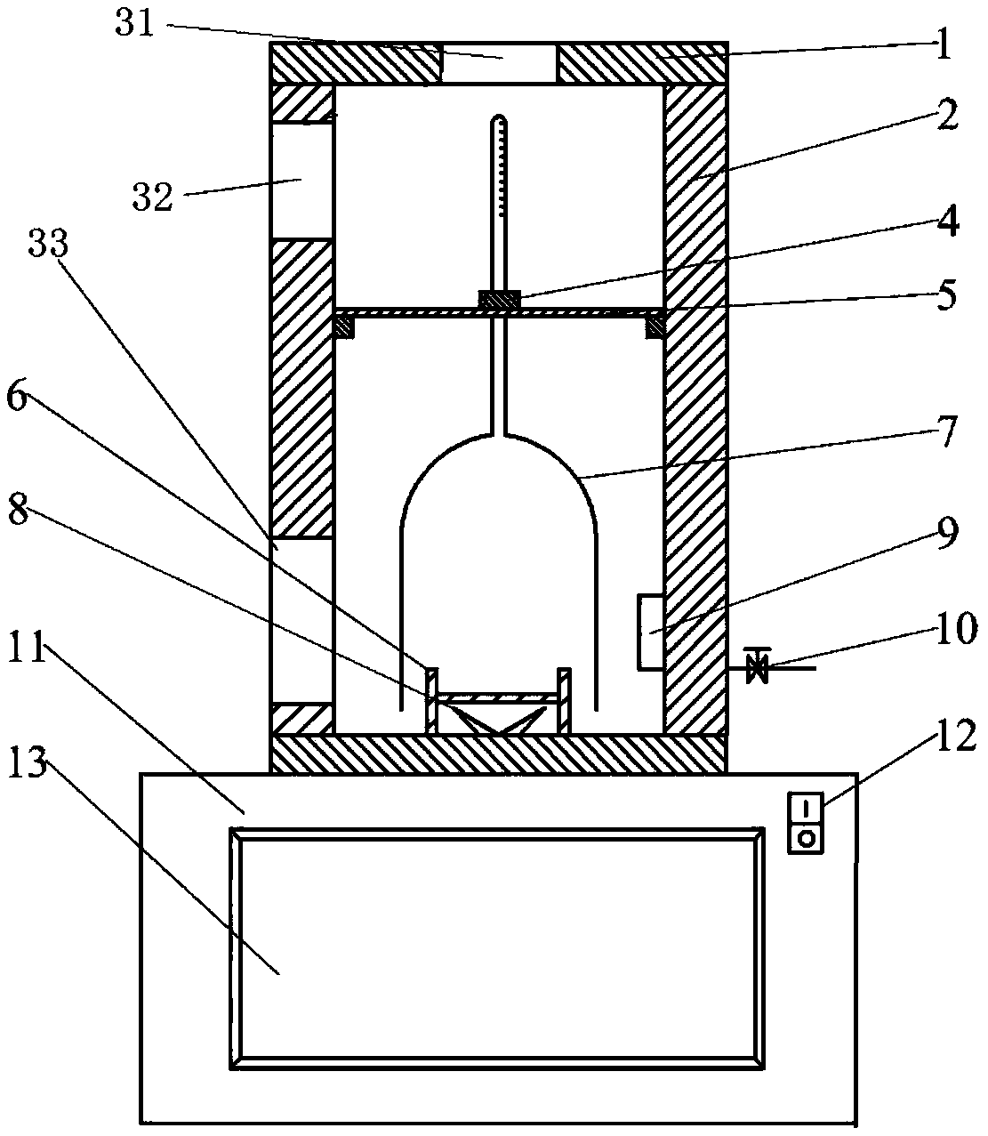
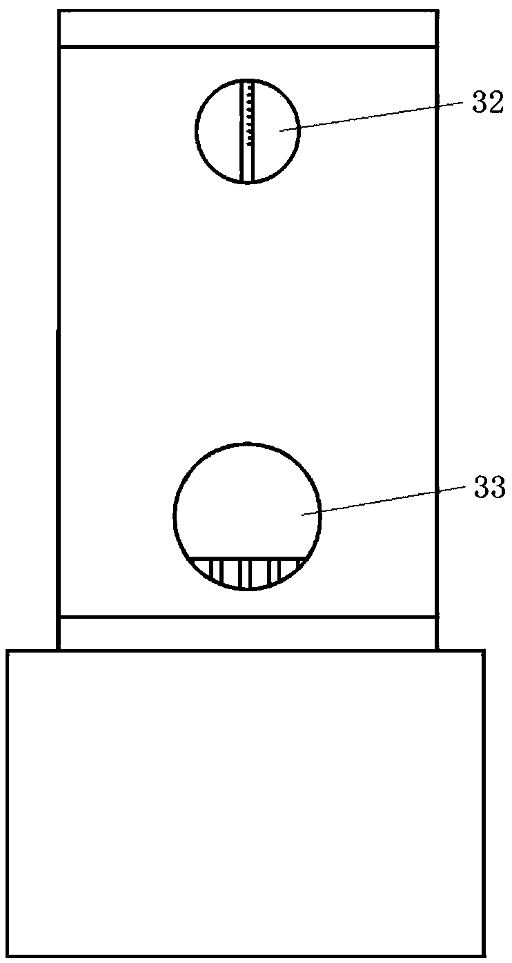
[0057] When using the visualized high-temperature and high-pressure imbibition extraction device of the present invention to carry out the imbibtion experiment, the imbibition device is placed vertically, and the high-temperature-resistant autoclave body is installed on the base, and the core saturated crude oil to be measured is aged for a period of time and placed On the clamping piece in the siphon bottle, and fix the clamping piece in the kettle body, the clamping piece is very stable through the fixed lock at the bottom of the kettle body, it will not rotate with the rotation of the fluid, but is fixed Motionless. The clamping piece can be adjusted axially and vertically according to the size of the core, and can hold It is a cylindrical core of 25-40mm. The clamping part is completely submerged in the experimental liquid. During the seepage process, the magnetic stirring device can be adjusted according to the experimental needs to make the rotor rotate, and then drive...

Embodiment 2

[0060] In order to explore whether the increase of the near-wall flow velocity has an effect on the imbibition process after the fluid in the kettle rotates, the experiment was designed according to the similar model, and the experiment of measuring the near-wall pressure was carried out by using a stainless steel core model with a pressure sensor on the peripheral wall. Jointly study the effect of increasing near-wall flow velocity on near-wall pressure. Table 1 lists the experimental results and numerical simulation results of the pressure near the wall of the simulated core wall pressure measuring point 1 and measuring point 2. Fig. 4(1) is the pressure distribution diagram of the experiment, and Fig. 4(2) is the numerical simulation Pressure distribution diagram.

[0061] Table 1 Comparison of experimental results and numerical simulation results of simulated core measurement of near-wall pressure

[0062]

[0063] From Table 1 and Figure 4(1) and Figure 4(2), it can be ...


PUM


Abstract

The invention relates to the field of petroleum exploitation and discloses an imbibition and extraction device. The imbibition and extraction device comprises a kettle body (2) and a kettle body cover(1), a baffle plate (5), a clamping part (6), an imbibition bottle (7), a stirrer (8) and a pressurizing port, wherein the kettle body cover and the kettle body are made from a high-temperature and high-pressure-resistant material; the baffle plate (5) is detachably arranged on the side wall of the kettle body; the clamping part (6) is arranged on the bottom face of the kettle body; the imbibition bottle (7) comprises a hood body and a metering tube, the hood body covers the clamping part, and the metering tube is fixedly arranged on the baffle plate; the stirrer (8) is fixed to the bottom face of the kettle body; and the pressurizing port is formed in the side wall of the kettle body; the stirrer is located below the clamping part and the stirrer is not in contact with the rock core clamped to the clamping part in the operating process. By stirring an experimental liquid through the stirrer, oil drops suspended on the rock core wall are peeled from the rock core wall to arrive at themetering tube of the imbibition bottle, so that the experimental data precision is improved greatly.

Description

technical field [0001] The invention relates to the field of petroleum exploitation, in particular to an imbibition extraction device used for studying the physical simulation experiment of imbibition extraction of tight oil in the exploitation of tight reservoirs. Background technique [0002] Conventional oil resources are gradually depleted, so tight oil is a very realistic oil replacement resource. Due to the small pore throats of tight reservoirs, imbibition phenomenon occurs under the action of capillary pressure, which can effectively exploit crude oil in small pores. Therefore, the study of imbibition phenomena in tight reservoirs is of great importance for further research on water injection development of tight reservoirs. theoretical significance and practical value. [0003] Traditional imbibition test methods include mass method and volume method. The mass method is to measure the amount of imbibition by relying on the quality difference of the core before and...

Claims


Application Information

Patent Timeline
IPC IPC(8): G01N15/08
CPCG01N15/082G01N15/0893
Inventor 于海洋芦鑫陈哲伟程时清
Owner CHINA UNIV OF PETROLEUM (BEIJING)
Why Eureka
Try Eureka