Device and method for measuring magnetoconstriction coefficient by using Doppler polarizer through sinusoidal modulation multi-beam laser heterodyne method

A technology of magnetostriction coefficient and Doppler vibrating mirror, applied in the field of micro-displacement detection, can solve the problem that the measurement accuracy cannot meet the requirements of ultra-precision measurement

Inactive Publication Date: 2012-02-15
HARBIN INST OF TECH
View PDF2 Cites 10 Cited by
  • Summary
  • Abstract
  • Description
  • Claims
  • Application Information

AI Technical Summary

Problems solved by technology

[0007] The purpose of the present invention is to solve the problem that the measurement accuracy of the existing magnetostrictive coefficient measurement method cannot meet the requirements...

Method used


Image

  • Device and method for measuring magnetoconstriction coefficient by using Doppler polarizer through sinusoidal modulation multi-beam laser heterodyne method
  • Device and method for measuring magnetoconstriction coefficient by using Doppler polarizer through sinusoidal modulation multi-beam laser heterodyne method
  • Device and method for measuring magnetoconstriction coefficient by using Doppler polarizer through sinusoidal modulation multi-beam laser heterodyne method

Examples


specific Embodiment approach 1

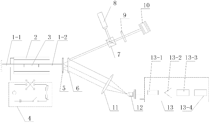
[0063] Specific implementation mode one: the following combination figure 1 Describe this embodiment, the device for measuring the magnetostriction coefficient by the Doppler galvanometer sinusoidal modulation multi-beam laser heterodyne in this embodiment, the device is composed of the first fixed rod 1-1, the second fixed rod 1-2, the excitation Coil 2, iron-nickel alloy sample to be tested 3, DC stabilized power supply 4, flat mirror 5, thin glass plate regardless of thickness 6, polarizing beam splitter PBS7, H 0 Composed of a solid-state laser 8, a quarter-wave plate 9, a vibrating mirror 10, a converging lens 11, a photodetector 12 and a signal processing system 13,

[0064] The DC stabilized power supply 4 is used to provide working power for the excitation coil 2, the iron-nickel alloy sample 3 to be tested is placed in the center of the excitation coil 2, and one end of the iron-nickel alloy sample 3 to be tested is fixedly connected to one end of the first fixed rod ...

specific Embodiment approach 2

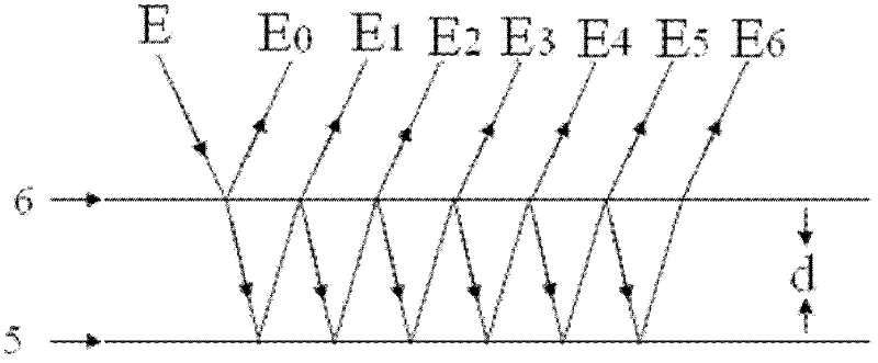
[0070] Embodiment 2: This embodiment is a further description of Embodiment 1, and the distance d is 20 mm.

specific Embodiment approach 3

[0071] Specific Embodiment 3: This embodiment is a further description of Embodiment 1 or 2. Both end surfaces of the first fixing rod 1-1 and the second fixing rod 1-2 are bonded with non-magnetic materials.


PUM

PropertyMeasurementUnit
Thicknessaaaaaaaaaa

Abstract

The invention discloses a device and a method for measuring a magnetoconstriction coefficient by using a Doppler polarizer through a sinusoidal modulation multi-beam laser heterodyne method, which belong to the technical field of micrometric displacement detection. By using the device and the method provided by the invention, the problem that the measurement precision of a conventional method for measuring the magnetoconstriction coefficient cannot meet an ultra-precise measurement requirement is solved. The method provided by the invention comprises the following steps: enabling a plane reflecting mirror and a thickness-regardless thin glass plate to be mutually parallel and equal-height, enabling a distance d between the thickness-regardless thin glass plate and the reflecting surface of the plane reflecting mirror to be 20mm, and turning on a driving power supply of a polarizer, so that the polarizer begins carrying out simple harmonic vibration; and collecting an electric signal output by a photoelectric detector through a signal processing system, processing a collected signal, obtaining a distance variable quantity between the plane reflecting mirror and the thickness-regardless thin glass plate, and obtaining the magnetoconstriction coefficient of an iron-nickel alloy sample to be measured according to the distance variable quantity. The device and the method provided by the invention are applicable to the measurement of the magnetoconstriction coefficient of a ferromagnetic body.

Description

technical field [0001] The invention relates to a device and method for measuring the magnetostriction coefficient by sinusoidally modulating a multi-beam laser heterodyne with a Doppler vibrating mirror, and belongs to the technical field of micro-displacement detection. Background technique [0002] The magnetic domains of ferromagnets are aligned under the action of an external magnetic field, causing changes in the lattice spacing in the medium, resulting in changes in the length of ferromagnets, which is called the magnetostrictive effect. Since this phenomenon was first discovered by the British physicist Joule in 1842, it is also called the Joule effect. The magnetostrictive effect not only has an important influence on the magnetism of the material, especially on the initial magnetic permeability and coercive force of the material, but also has a wide range of practical applications. For example, the magnetostrictive technology can It is used in mechanical vibration...

Claims


Application Information

Patent Timeline
IPC IPC(8): G01R33/18
Inventor 李彦超王春晖高龙曲杨丛海芳邵文冕
Owner HARBIN INST OF TECH
Why Eureka
Try Eureka