Non-destructive dynamic monitoring sensor for corrosion of reinforcing steel bar in concrete based on magnetic field and system

A technology for monitoring sensor and steel corrosion, applied in the direction of material magnetic variables, etc., can solve problems such as monitoring systems that do not accurately determine the corrosion rate of steel bars, high requirements for operator proficiency, and inability to quantitatively measure the corrosion rate of steel bars. Easy to operate on site, small size, high precision and stability

Inactive Publication Date: 2019-02-22
ZHEJIANG UNIV +1
View PDF8 Cites 26 Cited by
  • Summary
  • Abstract
  • Description
  • Claims
  • Application Information

AI Technical Summary

Problems solved by technology

However, the half-cell potential method gives the corrosion rate of the steel bar instead of the corrosion rate of the steel bar. At the same time, the accuracy of the half-cell point detection is not high, and there are high requirements for the operator's proficiency.
Acoustic emission steel corrosion detection method and half-cell potential method, acoustic emission technology can only determine the probability of corrosion qualitatively based on parameters such as the cumulative impact number (AEN), but cannot quantitatively measure the corrosion rate of steel bars
In actual engineering, there is still no monitoring system to accurately determine the corrosion rate of steel bars

Method used


Image

  • Non-destructive dynamic monitoring sensor for corrosion of reinforcing steel bar in concrete based on magnetic field and system
  • Non-destructive dynamic monitoring sensor for corrosion of reinforcing steel bar in concrete based on magnetic field and system
  • Non-destructive dynamic monitoring sensor for corrosion of reinforcing steel bar in concrete based on magnetic field and system

Examples


Embodiment Construction

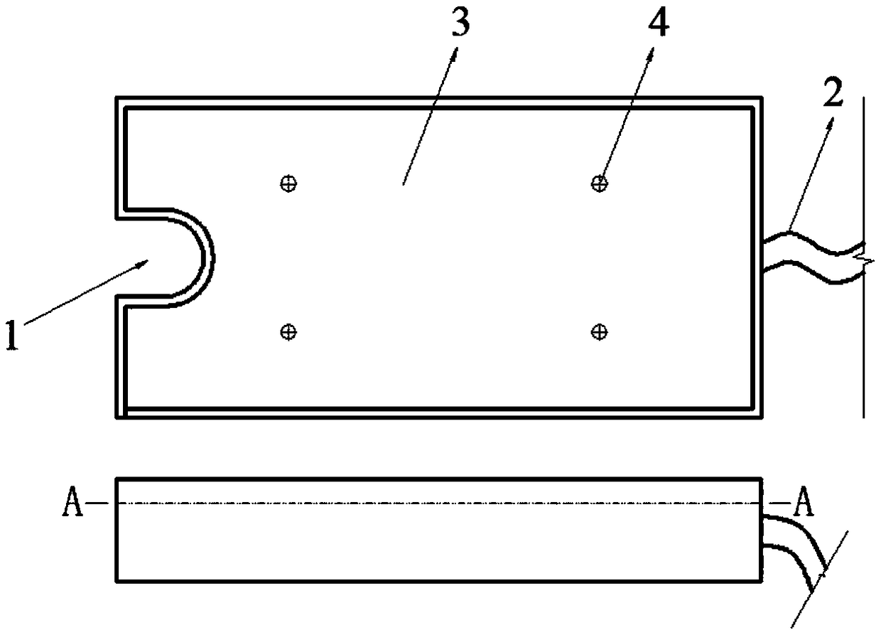
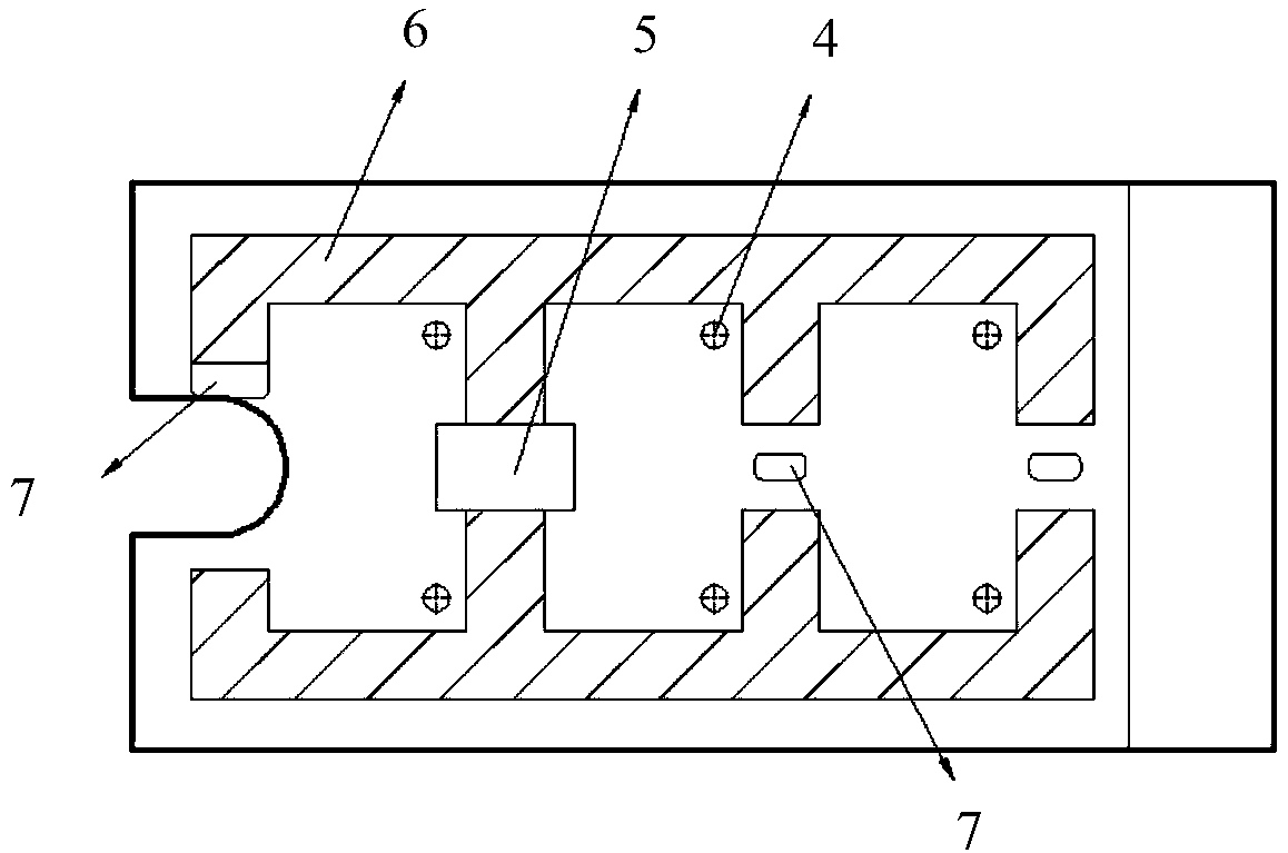
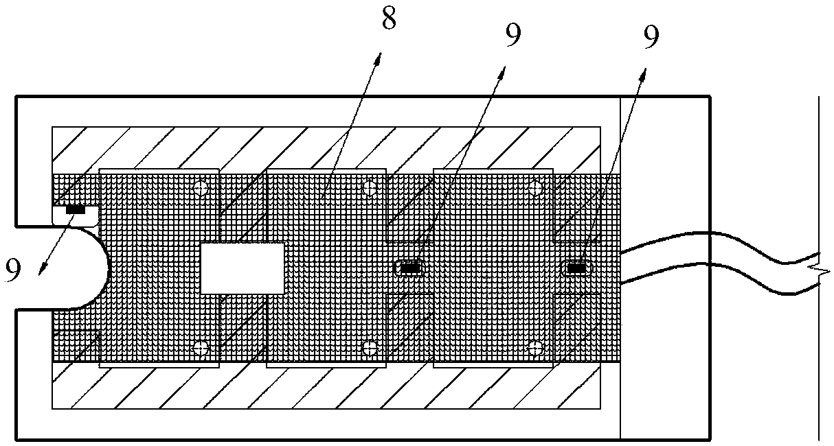
[0034] As shown in the figure, the non-destructive dynamic monitoring sensor for steel bar corrosion in concrete based on the magnetic field includes a hollow box-shaped shell; one end of the shell is provided with a bayonet groove 1 for clamping the steel bar to be tested; there are two in the shell with The stainless steel frame 6 with mountain-shaped protruding teeth and opposite arrangement, except that permanent magnets 5 are arranged between one group of relative teeth, the installation position (card slot 7) of Hall sensor 9 is reserved between other relative teeth, permanent magnet 5 Also fits in a matching card slot. On both sides of the bayonet groove 1, the opposite teeth of the ends of the stainless steel frame 6 and the installation position of a Hall sensor are arranged; there is also a data acquisition board 8 connected to the six-core cable 2 in the housing, and the Hall sensor 9 All are fixed on the data acquisition board 8, and its main body is located in the...


PUM


Abstract

The invention relates to the monitoring technique of corrosion of reinforcing steel bars in construction engineering, and aims to provide a non-destructive dynamic monitoring sensor for corrosion of areinforcing steel bar in concrete based on a magnetic field and a system. A slot for clamping a to-be-detected reinforcing steel bar is formed in one end of a shell of the sensor; two epsilon-type protruding teeth and oppositely arranged stainless steel frames are arranged in the shell, and mounting positions of Hall sensors are retained among other opposite teeth beside a permanent magnet arranged between one opposite teeth; end opposite teeth of the stainless steel frame and a mounting position of a Hall sensor are arranged on two sides of the slot, the Hall sensors are fixed to a data collection plate and the main body parts are located in the mounting positions. The corrosion rate of the reinforcing steel bar is monitored by mean of a magnetic field principle, so that the precision and the stability are relatively high; non-destructive and dynamic monitoring of the corrosion rate of the reinforcing steel bar in concrete can be achieved. The corrosion rate of the reinforcing steelbar in concrete can be given directly quantitively. The instrument device is small in size, convenient to carry and convenient to operate in an engineering site.

Description

technical field [0001] The invention relates to a steel bar corrosion monitoring technology in construction engineering, in particular to a magnetic field-based non-destructive dynamic monitoring sensor and system for steel bar corrosion in concrete. Background technique [0002] Due to the advantages of concrete structure in terms of materials, cost and maintenance, it has always occupied a dominant position in civil engineering, and has been widely used in major civil engineering (large-scale construction projects, bridge engineering, hydraulic engineering and port engineering). For a long time, the corrosion of steel bars has been the main factor affecting the durability of reinforced concrete structures, especially for concrete structures in marine environments and deicing salt environments. The corrosion of steel bars is often very serious, which will lead to cracking and damage of concrete structures. The economic losses caused by the durability of concrete structures ...

Claims


Application Information

Patent Timeline
Patent Type & Authority Applications(China)
IPC IPC(8): G01N27/82
CPCG01N27/82
Inventor 李宗津曹香鹏刘超金南国田野高荣森
Owner ZHEJIANG UNIV
Why Eureka
Try Eureka