
Wireless communication circuit protection structure

A wireless communication and circuit protection technology, applied in the direction of circuits, electrical components, waveguides, etc., can solve the problem of anti-static discharge and anti-leakage function and wireless communication function mutually exclusive, internal system grounding and external grounding cannot be separated, internal system system failure and other issues, to achieve the effect of preventing leakage function and wireless communication function, anti-static discharge leakage function and wireless communication function

Inactive Publication Date: 2019-02-22
MOXA INC
View PDF5 Cites 0 Cited by
  • Summary
  • Abstract
  • Description
  • Claims
  • Application Information

AI Technical Summary

Problems solved by technology

[0016] However, for the above-mentioned wireless communication circuit structure, one of the characteristics lies in the integrity of the wireless communication signal line and the grounding line. The loss (Loss) is close to 0dB, which has a good wireless communication effect. However, due to the integrity of the wireless communication signal line and the grounding line, the internal system ground and the external ground cannot be separated, that is, the above-mentioned wireless communication circuit structure has no way to provide resistance. Electromagnetic susceptibility (EMS) interference, anti-electrostatic discharge (ESD) and ability to prevent leakage, which will cause internal systems to be affected by electromagnetic susceptibility interference and electrostatic discharge, resulting in system failure or even damage
[0017] In order to provide anti-electromagnetic susceptibility interference, anti-static discharge and anti-leakage capabilities, it is necessary to separate the wireless communication signal line and the grounding line in the above-mentioned wireless communication circuit structure, in the wireless communication frequency range of 800MHz to 6GHz The loss in the medium is greater than 30dB, that is, the effect of wireless communication cannot be provided
[0018] In summary, it can be seen that there have been problems in the existing wireless communication circuit structure for a long time, such as anti-electromagnetic susceptibility interference, anti-static discharge, and anti-leakage functions and wireless communication functions. Therefore, it is necessary to propose an improved technology means to solve this problem

Method used


Image

  • Wireless communication circuit protection structure
  • Wireless communication circuit protection structure
  • Wireless communication circuit protection structure

Examples


Embodiment Construction

[0073] The implementation of the present invention will be described in detail below with reference to the drawings and examples, so as to fully understand and implement the implementation process of how to use technical means to solve technical problems and achieve technical effects in the present invention.

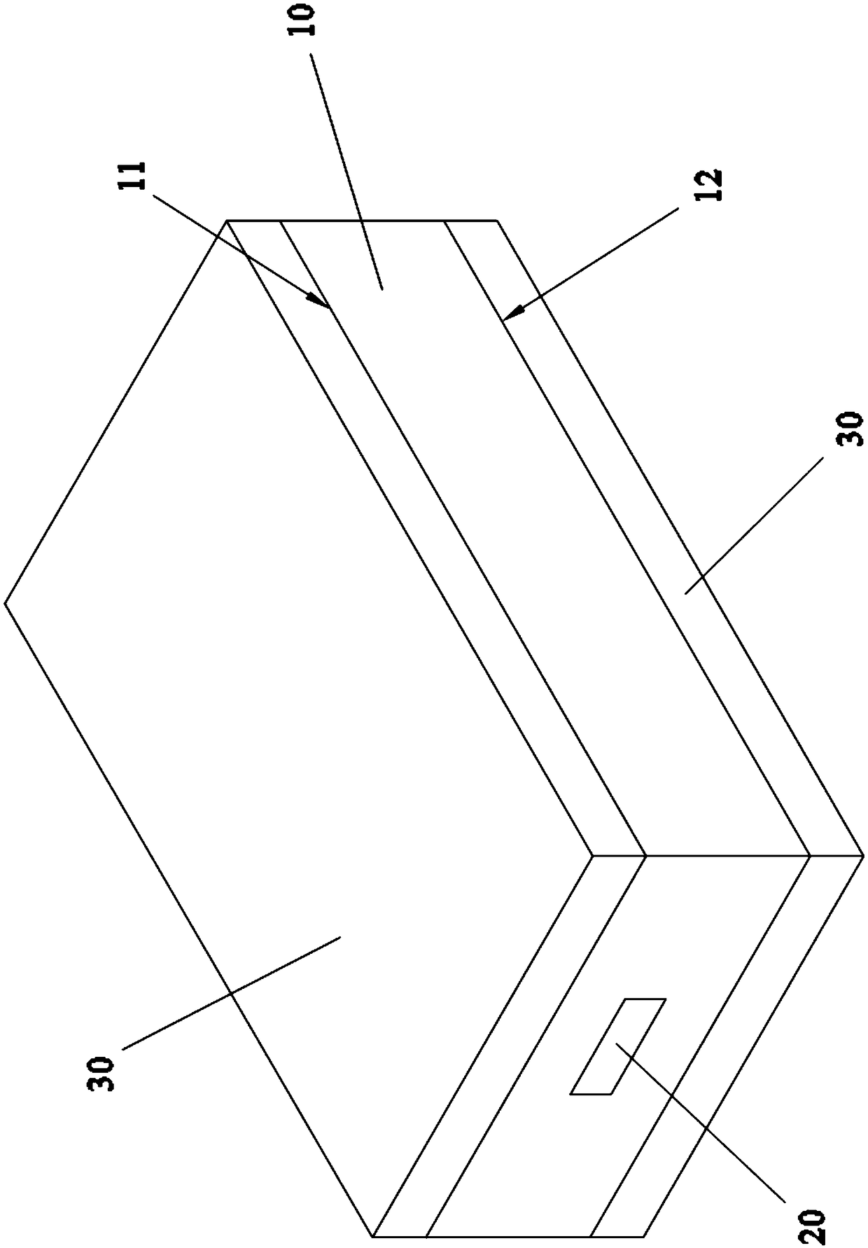
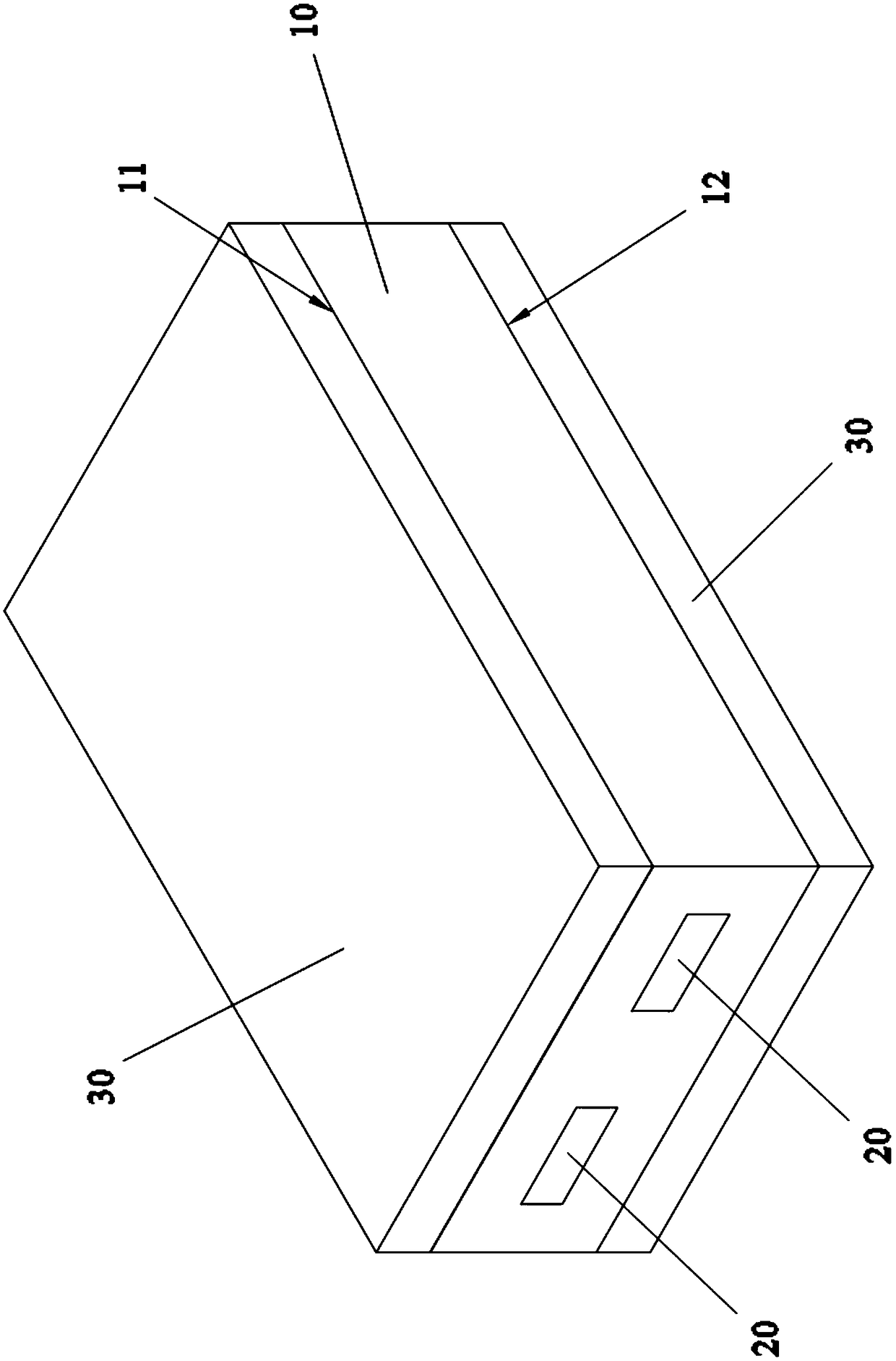
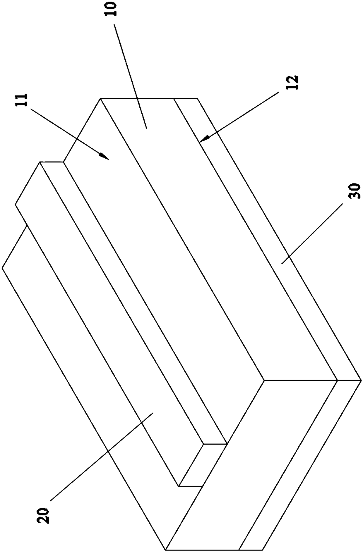
[0074] The first embodiment of the wireless communication circuit protection structure disclosed in the present invention will be described at first below, and please refer to Figure 2A to Figure 2C as shown, Figure 2A It is a perspective schematic diagram of a first perspective view of the first embodiment of the wireless communication circuit protection structure of the present invention; Figure 2B It is a perspective schematic diagram of the second perspective view of the first embodiment of the wireless communication circuit protection structure of the present invention; Figure 2C It is the measured data diagram of the first embodiment of the wireless communica...


PUM


Abstract

The invention discloses a wireless communication circuit protection structure. By improving a microstrip line structure and jointly improving the microstrip line structure and a coplanar waveguide structure, an external ground and an internal system ground can be completely separated, thereby achieving a technical effect that a wireless communication circuit structure has an anti-electromagnetic sensitivity interference function, an anti-electrostatic discharge function, an anti-electric leakage function.

Description

[0001] This application is a divisional application of the original invention application (application number 201310752647.5, application date December 31, 2013), and the invention name of the original application is "wireless communication circuit protection structure". technical field [0002] The invention relates to a circuit protection structure, in particular to a circuit protection structure for wireless communication. Background technique [0003] For the existing wireless communication circuit structure, there are stripline (Stripline) structure, stripline coupling (Coupled Stripline) structure, microstrip line (Microstrip) structure, microstrip line coupling (Coupled Microstrip) structure, coplanar waveguide ( CPW) structure and coplanar waveguide (CPW Ground) structure with ground plane...etc. [0004] Please refer to Figure 1A as shown, Figure 1A It is a three-dimensional schematic diagram of the existing stripline structure. [0005] The substrate 10 of the s...

Claims


Application Information

Patent Timeline
Patent Type & Authority Applications(China)
IPC IPC(8): H01P3/00
Inventor 洪传恩刘信宏
Owner MOXA INC
Learn More