Robot eye adopting visual cone coordinate system for vibration zooming
A robot and zoom mechanism technology, applied to instruments, cameras, manipulators, etc., can solve the problem that the effect cannot be compared with the human eye, and achieve the effect of reducing the amount of calculation and the space for storing data
- Summary
- Abstract
- Description
- Claims
- Application Information
AI Technical Summary
Problems solved by technology
Method used
Image

Examples
Embodiment Construction
[0065] The first embodiment of the present invention is a robot eye with a spherical image sensor:
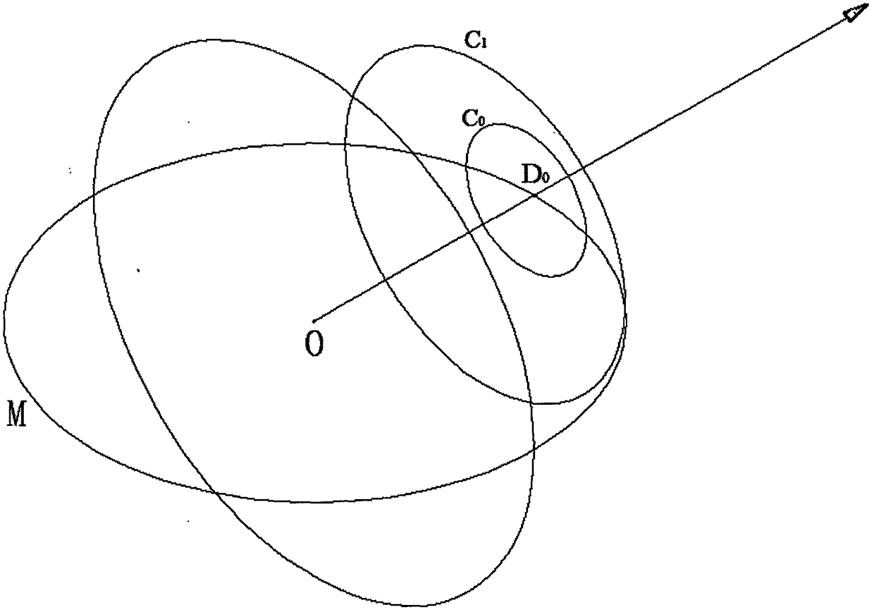
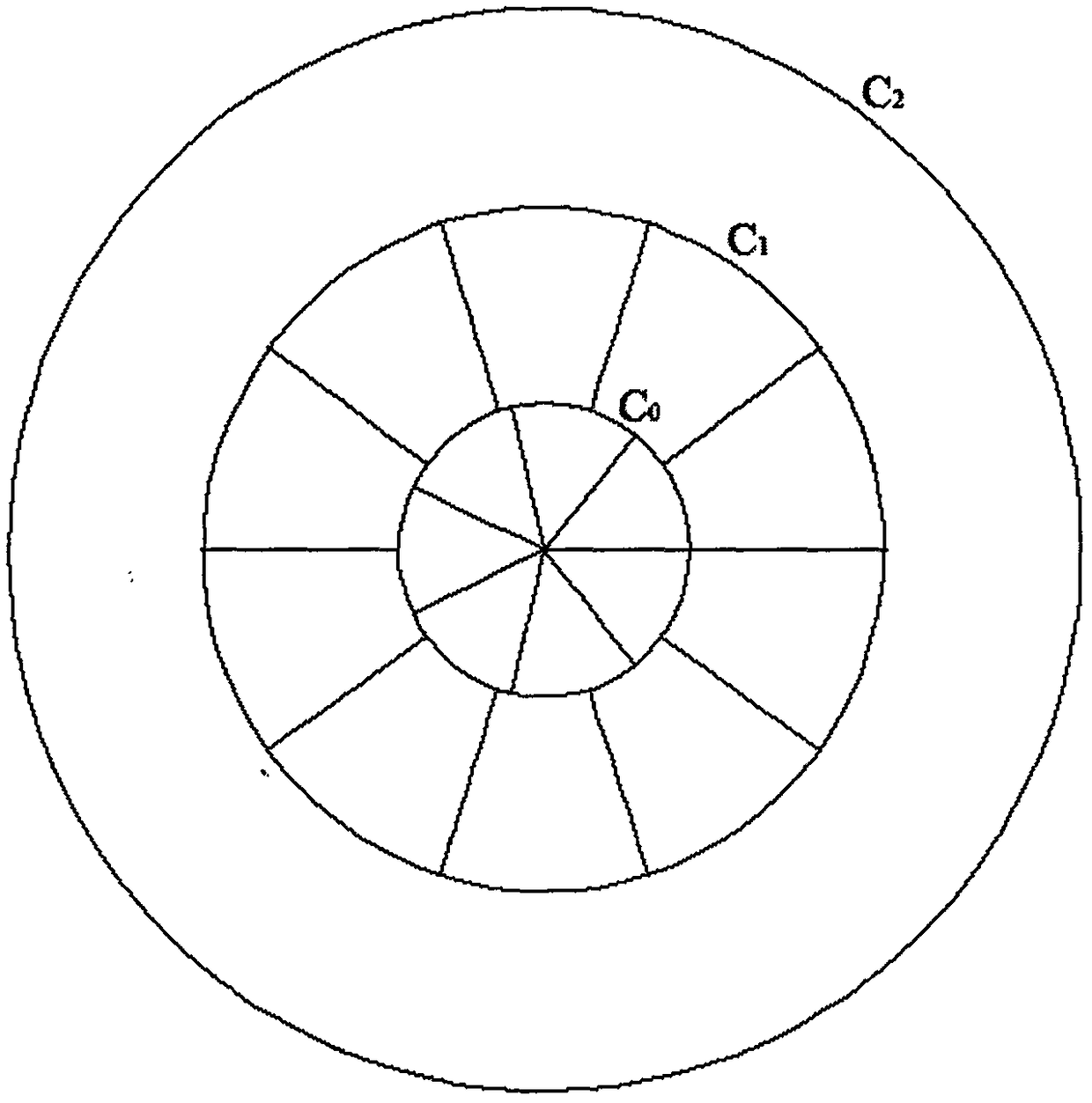
[0066] see Figure 11 , the robot eye is composed of a lens 1, a vibration zoom mechanism 2, a spherical image sensor 4, a vision chip, and a power supply; in the vibration zoom mechanism 2, the lens 3 is embedded in a magnet and is in a vacuum cavity. When working, the vibration The electromagnet in the zoom mechanism 2 produces a periodically changing alternating magnetic field, and the alternating magnetic field generates an interaction force with the magnet stuck on the lens 3, forcing the magnet stuck on the lens 3 and the lens 3 to vibrate periodically, and the vision During the calculation process, the chip divides the field of view according to the latitude and longitude division method. At this time, the clearest position parameter in the cone coordinates is the distance from the origin O to the object surface. This parameter is actually the length value of the polar c...
PUM
 Abstract
Description
Claims
Application Information
 - R&D
- Intellectual Property
- Life Sciences
- Materials
- Tech Scout
- Unparalleled Data Quality
- Higher Quality Content
- 60% Fewer Hallucinations
Browse by: Latest US Patents, China's latest patents, Technical Efficacy Thesaurus, Application Domain, Technology Topic, Popular Technical Reports.
© 2025 PatSnap. All rights reserved.Legal|Privacy policy|Modern Slavery Act Transparency Statement|Sitemap|About US| Contact US: help@patsnap.com