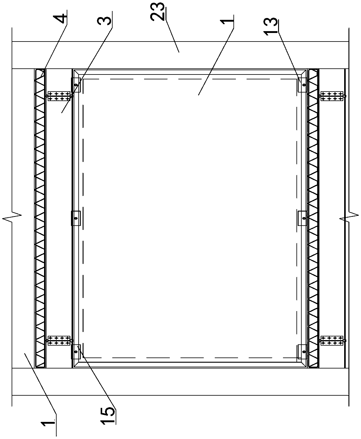
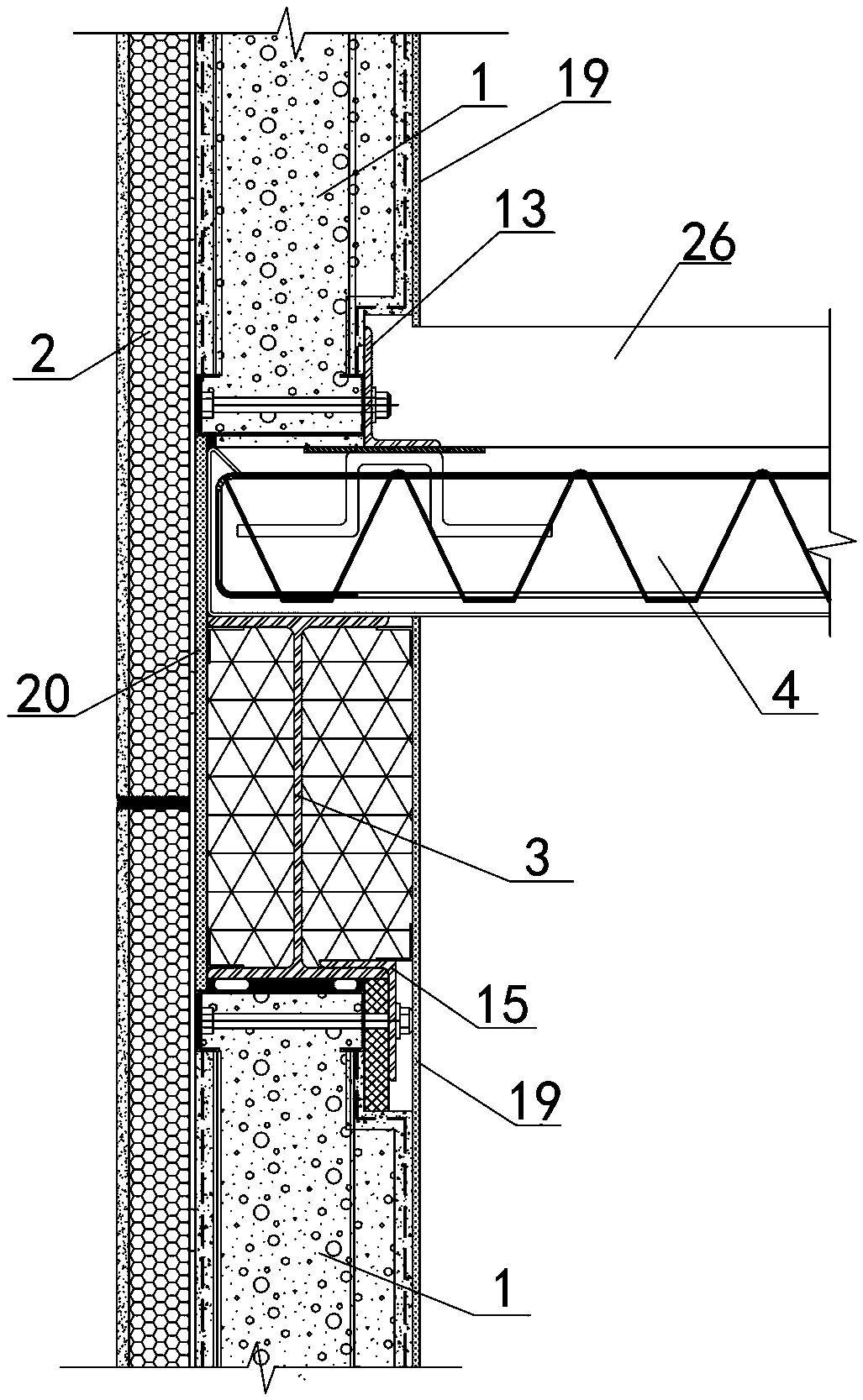
[0048] Examples see figure 1 As shown, a prefabricated steel frame exterior wall system includes a steel frame exterior wall panel 1 and an externally hung thermal insulation and decoration integrated panel 2, and also includes a horizontal structure enclosed and fixed on the upper and lower sides of the steel frame exterior wall panel. The horizontal structure includes the steel beam 3 on the lower side and the steel truss floor slab 4 on the upper side, see Figure 2-3 As shown, the steel frame exterior wall panel includes a core material 11 and a frame frame 12. In this embodiment, the sheet skin is 20mm thick and dense foamed cement, and the core material is low-density foamed cement mixed with polystyrene particles.
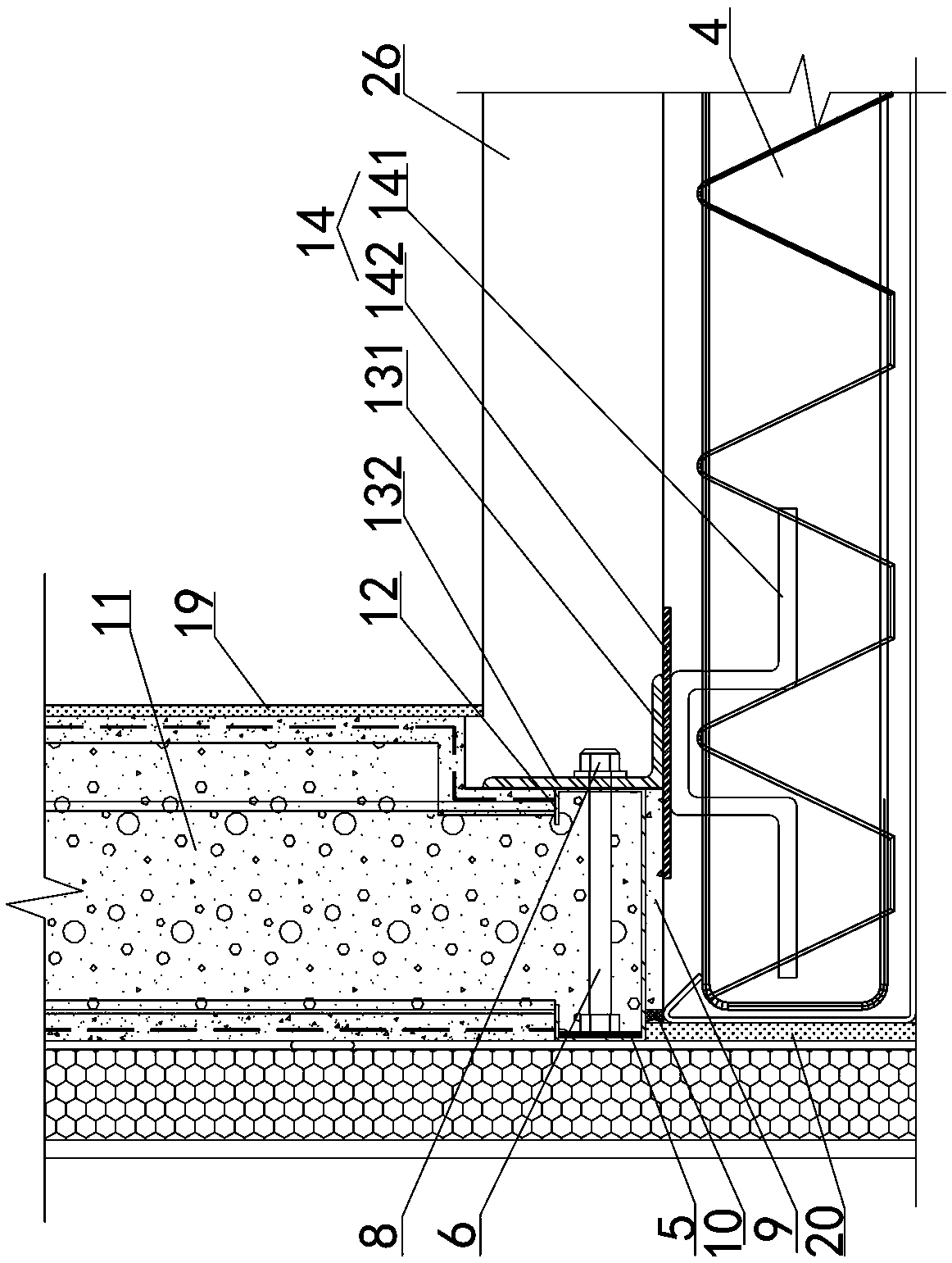
[0049] See figure 2 As shown, the upper side of the steel frame exterior wall panel is connected to steel beams through an upper connecting structure, the lower side of the steel frame exterior wall panel is connected to a steel truss floor panel through a lower connecting structure, and the frame frame 12 is a coil Side C-shaped steel, the opening faces the center of the core material, and the four peripheral parts of the outer wall panel of the steel frame are concave inward and 60 mm lower than the surface. See Figure 2-3 As shown, the frame frames are all pre-buried in the core material of the inner recess.
[0050] See Figure 2-4 with Image 6 As shown, the frame frame includes an inner vertical bending plate 121, a horizontal plate 122, and an outer vertical bending plate 123. The inner wall of the outer vertical bending plate 123 is welded with a set of reinforcing steel plates 5 of the same height. The middle part of 5 is welded with a horizontal connecting screw 6, the connecting screw penetrates the inner vertical bending plate 121, and the inner end of the connecting screw 6 is provided with external threads and fitted with a washer 7 and a nut 8.
[0051] See image 3 As shown, the bottom of the outer wall panel of the steel frame is located above the steel truss floor panel with a gap. The reserved gap is filled with fine stone anti-cracking concrete 9, and the end of the gap is sealed by weathering glue 10. The mark of the fine stone anti-cracking concrete 9 is higher than the mark of the wall board.
[0052] See image 3 , Figure 9-10 As shown, the lower connecting structure corresponds to the connecting screw along the width direction of the outer wall panel of the steel frame, and includes a lower connecting angle 13 close to the bottom edge of the outer wall of the steel frame, and also includes a lower connecting angle one-to-one. Corresponding to the embedded component 14 in the steel truss floor slab, the opening of the lower connecting angle steel 13 faces away from the wall, and includes a lower horizontal leg 131 and a lower vertical leg 132. The lower side of the lower horizontal leg 131 and the embedded The component 14 is fixedly connected, the outer side of the lower vertical limb 132 is close to the surface of the inner recess of the bottom edge of the outer wall panel of the steel frame, and the connecting screw of the inner recess penetrates the lower vertical limb 132 and is on the inner side of the lower vertical limb Fasten with washer 7 and nut 8. An oblong hole is opened on the lower vertical limb 132, and the connecting screw passes through the hole.
[0053] See image 3 , Figure 7-8 As shown, the pre-embedded assembly 14 includes a lower vertical bolster 141 and an upper horizontal connecting steel plate 142. The hex bolster is arranged in two parallel rows. The top of the hex bolster 141 and the connecting steel plate 142 The bottom is welded, the linear bolster 141 is embedded in the steel truss floor slab 4, and the upper surface of the connecting steel plate 142 is flush with the upper surface of the steel truss floor slab 4.
[0054] See Figure 4 , Figure 11-12 As shown, the upper connecting structure is arranged at intervals along the width direction of the outer wall panel of the steel frame, and corresponds to the lower connecting structure one-to-one. The upper connecting structure includes an upper connecting angle steel 15 welded on the lower flange of the steel beam, and also includes The rubber pad 16, the opening of the upper connecting angle facing the wall, includes an upper horizontal limb 151 and an upper vertical limb 152. The lower side of the upper horizontal limb 151 is fixedly connected to the upper side of the lower flange 31 of the steel beam. The end of the lower flange 31 of the steel beam presses against the inner side of the upper vertical leg 152, and the outer side of the upper vertical leg 152 has a gap with the inner recess of the top edge of the outer wall panel of the steel frame, and the gap is filled with The rubber pad 16, the top end of the rubber pad 16 presses against the lower flange 31 of the steel beam, the bottom end of the rubber pad 16 extends downward to abut and cover the inner recess of the top edge of the outer wall panel of the frame. The connecting screw 6 passes through the rubber pad 16 and the upper vertical limb 152 and is fastened on the inner side of the upper vertical limb by a washer 7 and a nut 8. The upper vertical limb 152 is provided with an oblong hole through which the connecting screw passes. The top side of the outer wall panel of the steel frame is located below the steel beam with a gap. The gap is provided with two rubber rods 17 arranged in the width direction of the wall. The polyurethane foaming agent 18 is used to solidify, the end of the gap is close to the rubber rod and is sealed by the weather resistant glue 10, and the rubber rod 17 and the polyurethane foaming agent 18 form a flexible connection.
[0055] See Figure 4 As shown, the upper and lower flange plates of the steel beam 3 and the two sides of the web are filled with rock wool 21, each corner of the rock wool is wrapped with reinforced angle steel 22, and the opening of the reinforced angle steel faces the belly board.
[0056] See Figure 2-4 As shown, the inner side of the steel frame outer wall panel is fixedly connected with an inner fiber cement board 19 which extends upward at the upper connecting structure to cover the inner side of the steel beam to the bottom of the steel truss floor board 4. The outer fiber cement board is located at the lower connecting structure to the building surface layer 26 on the upper side of the steel truss floor board 4, and the thickness of the inner fiber cement board 19 is 8 mm.
[0057] See Figure 2-4 As shown, the outer side of the steel frame outer wall panel is fixedly connected with an outer fiber cement board 20, and the outer surface of the outer fiber cement board 20 is flush with the outer surface of the steel frame outer wall panel, and is arranged on the outer side of the horizontal structure. At the same height as the horizontal structure, the thermal insulation and decoration integrated board 2 is fixedly connected to the outside of the outer fiber cement board 20 at the horizontal structure. The thickness of the outer fiber cement board 20 is 10 mm.
[0058] See Figure 5 As shown, the system also includes a vertical structure enclosed and fixed on the left and right sides of the outer wall panel of the steel frame. The vertical structure includes a concrete-filled steel tube column 23. A gap is reserved between the columns, and the gap between the reserved gaps is provided with two rubber rods 17 arranged along the height of the wall. The two rubber rods are solidified by polyurethane foaming agent 18. The ends of the gap The rubber rod is blocked by the weather resistant glue 10, and the rubber rod and the polyurethane foaming agent form a flexible connection.
[0059] See Figure 5 The outer corners of the concrete-filled steel tube column 23 protruding from the outer wall panel of the steel frame are fixedly connected with a vertical installation keel 24. The outer side of the installation keel is surrounded by a column outer fiber cement board 25, and the column outer fiber cement The outer side of the board 25 and the outer side of the steel frame exterior wall panel are connected with a thermal insulation and decorative integrated board 2.
[0060] The construction method of this fabricated steel frame exterior wall system is as follows:
[0061] Step one, design the number and position of the upper and lower connecting structures, and then prefabricate the outer wall panel 1 of steel frame in the factory. The perimeter of the panel is composed of crimped C-shaped steel to form the frame frame 12, according to the position of the connecting structure. The reinforcing steel plate 5 and the connecting screw 6 are welded in groups on the side frame frame at intervals, and the core material around the plate is concave;
[0062] Step two, construct the steel truss floor slab, and construct the embedded component 14 at the lower connecting structure position;
[0063] Step 3: Align the bottom of the steel frame exterior wall panel with the upper side of the end of the steel truss floor slab, pour a layer of fine stone anti-cracking concrete 9 on the end of the steel truss floor slab, and then seat the bottom of the steel frame external wall panel firmly The fine-stone anti-cracking concrete 9 is cushioned by a wooden square of equal height; the size of the wooden square is length×width×height=200mm×50mm×15mm, and 15mm thick high-grade fine-stone anti-cracking concrete is poured;
[0064] Step 4: Weld the lower horizontal limb 131 of the lower connecting angle steel with the embedded assembly 14, where the connecting screw 6 passes through the lower vertical limb 132 and then is anchored by the gasket 7 and the nut 8;
[0065] Step 5. After the fine-stone anti-cracking concrete 9 is initially set, pull out the wood and apply weather-resistant glue 10 on the outside of the fine-stone anti-cracking concrete to fill the joints;
[0066] Step 6, weld the connecting angle steel 15 on the lower flange 31 of the steel beam corresponding to the position of the upper connecting structure;
[0067] Step 7: Align the top of the outer wall panel of the steel frame with the lower side of the steel beam and reserve the installation seam, the height of the installation seam is 20mm, and then insert the rubber pad 16 in the concave position of the place, where the connecting screw 6 passes through the rubber The pad 16 and the upper vertical limb 152 of the upper connecting angle steel are anchored by a washer 7 and a nut 8;
[0068] Step 8. Insert a rubber rod 17 into the installation seam. The position where the rubber rod 17 is squeezed is more than 10mm away from the edge of the wall panel. Then, fill the polyurethane foaming agent 18 between the rubber rods 17, and finally use weather resistance on the outside of the rubber rod 17. Glue 10 caulking;
[0069] Step 9: Set aside installation seams between the left and right sides of the outer wall panel of the steel frame and the concrete-filled steel tube column. Insert the rubber rod 17 into the installation seam. The rubber rod 17 is squeezed into the wall ≥10mm from the edge of the wall, and then the rubber rod Fill the space between 17 with polyurethane foaming agent 18, and finally use weather-resistant glue 10 to fill the joints on the outside of the rubber rod 17;
[0070] Step 10: Fill the steel beam 3 with rock wool 21, and then install the inner fiber cement board 19 and the outer fiber cement board 20 in layers;
[0071] Step eleven, install the thermal insulation and decoration integrated board 2 outdoors;
[0072] Step 12, construct the building surface layer 26 indoors.