Resistance element lead pin shear-formation device and method

A resistor and pin technology, applied in the field of resistor pin shearing and forming devices, can solve the problems of complex structure of pin shearing products, low cutting precision, and poor versatility, and achieve simple structure and strong versatility , low cost effect

Pending Publication Date: 2019-03-01
中船重工西安东仪科工集团有限公司
View PDF12 Cites 4 Cited by
  • Summary
  • Abstract
  • Description
  • Claims
  • Application Information

AI Technical Summary

Problems solved by technology

For enterprises with a small production volume, the cutting of the pins of electronic components is done manually by workers. Manual cutting has problems of low efficiency, poor consistency, and low cutting accuracy.
[0004] At present, in view of the p

Method used


Image

  • Resistance element lead pin shear-formation device and method
  • Resistance element lead pin shear-formation device and method
  • Resistance element lead pin shear-formation device and method

Examples


Embodiment 1

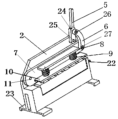
[0044] according to Figure 1-10 A kind of resistance pin shearing forming device described, comprises

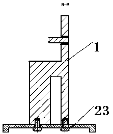
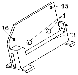
[0045] The mounting bracket 1 is composed of a wall plate 2 and a storage table 3. The wall plate 2 is arranged on the axial side of the storage table 3. The wall plate and the storage table are an integral structure. limit column 4;

[0046] A driving member is rotatably connected to one end of the wall plate 2;

[0047] A shearing mechanism, one end of the shearing mechanism is rotatably connected to the wall plate 2, and the other end of the shearing mechanism is rotatably connected to the driving member;

[0048] The clamping mechanism is connected to the upper surface of the storage table, and its rear side wall is in contact with the two limit posts 4. The upper surface of the clamping mechanism is higher than the lower edge of the shearing mechanism, and is used to clamp the resistance to be sheared;

[0049] A locking mechanism, the locking mechanism is connected...

Embodiment 2

[0053] according to figure 1 The above-mentioned resistance pin shearing and forming device is different from the first embodiment in that: the driving member includes a handle 5 and a connecting rod 6; the lower part of the handle 5 has a sixth through hole 24 from top to bottom and the seventh through hole 25, the eighth through hole 26 and the ninth through hole 27 are respectively opened at the two ends of the connecting rod 6; the handle 5 and the connecting rod 6 are rotationally connected through the sixth through hole 24 and the eighth through hole 26; the handle 5 is rotatably connected to one end of the wall plate 2 through the seventh through hole 25, and the connecting rod 6 is rotatably connected to the shearing mechanism through the ninth through hole 27.

[0054] When starting pin cutting, a rotational torque is applied to the handle 5, and the torque is transmitted to the shearing mechanism through the connecting rod 6, and the resistance pin is sheared. The d...

Embodiment 3

[0056] according to figure 1 , Figure 4 , Figure 5 , Figure 7 and Figure 8 The above-mentioned resistance pin shearing and forming device is different from the first embodiment in that: the shearing mechanism includes a knife holder 7 and a pressing mechanism; two ends of the knife holder 7 are respectively provided with a second A through hole 11 and a second through hole 28, the bottom of the tool holder 7 has a cutting edge, the cutting edge is a semicircle with a bell mouth, and the upper edge of the cutting edge is lower than the upper surface of the clamping mechanism; One end of the knife rest 7 is rotatably connected with the middle part of the other end of the wall plate 2 through the first through hole 11, and the other end of the knife rest 7 is rotatably connected with the shearing mechanism through the second through hole 28; It matches with the clamping mechanism; the pressing mechanism is fixedly connected to the outer surface of the tool holder 7, and t...


PUM


Abstract

The invention belongs to the technical field of assembly of electronic elements and particularly relates to a resistance element lead pin shear-formation device and a resistance element lead pin shear-formation method. By organic combination of a mounting bracket, a driving part, a shearing mechanism, a clamping mechanism and a locking mechanism, the invention provides a resistance element lead pin shear-formation device which is simple in structure, low in cost, flexible and convenient to operate. The resistance element lead pin shear-formation device realizes high shear-formation precision,high formation efficiency and high universality of a resistor. The resistor shorn by the resistance element lead pin shear-formation device provided by the invention is good in consistency and meets the technological requirements.

Description

technical field [0001] The invention belongs to the technical field of assembly of electronic components, and in particular relates to a resistance pin cutting and forming device and method. Background technique [0002] At present, the assembly requirements for components on the circuit board are getting higher and higher. Therefore, it is often necessary to cut the pins of the electronic components before the circuit board assembly, so as to ensure that the height of the electronic components from the circuit board is consistent and meets the relevant requirements when the electronic components are inserted. [0003] The purpose of shear forming of component leads is to mechanically deform the leads of components into the expected shape, so as to meet the process requirements in the assembly process of components. For enterprises with a small production volume, the cutting of the pins of electronic components is done manually by workers. Manual cutting has the problems of...

Claims


Application Information

Patent Timeline
IPC IPC(8): B21F11/00
CPCB21F11/00
Inventor 强春晓田杜养耿鹏飞谢志斌
Owner 中船重工西安东仪科工集团有限公司
Why Eureka
Try Eureka