Forging equipment for small hardware production

A technology for small hardware and equipment, applied in the field of forging equipment for small hardware production, can solve the problems of difficulty in ensuring consistent rotation angles, insufficient safety, etc., and achieve the effects of sufficient forging, strong adaptability, and improved forging efficiency.

Inactive Publication Date: 2019-03-01
黄连芝
View PDF6 Cites 3 Cited by
  • Summary
  • Abstract
  • Description
  • Claims
  • Application Information

AI Technical Summary

Problems solved by technology

[0004] In the production of hardware, the workpiece needs to be forged. However, the existing forging equipment generally rotates the forged workpiece manually. On the one hand, it is not safe enough; on the other hand, it is difficult to ensure that the rotation angle is consistent every time.

Method used


Image

  • Forging equipment for small hardware production
  • Forging equipment for small hardware production
  • Forging equipment for small hardware production

Examples


Embodiment 1

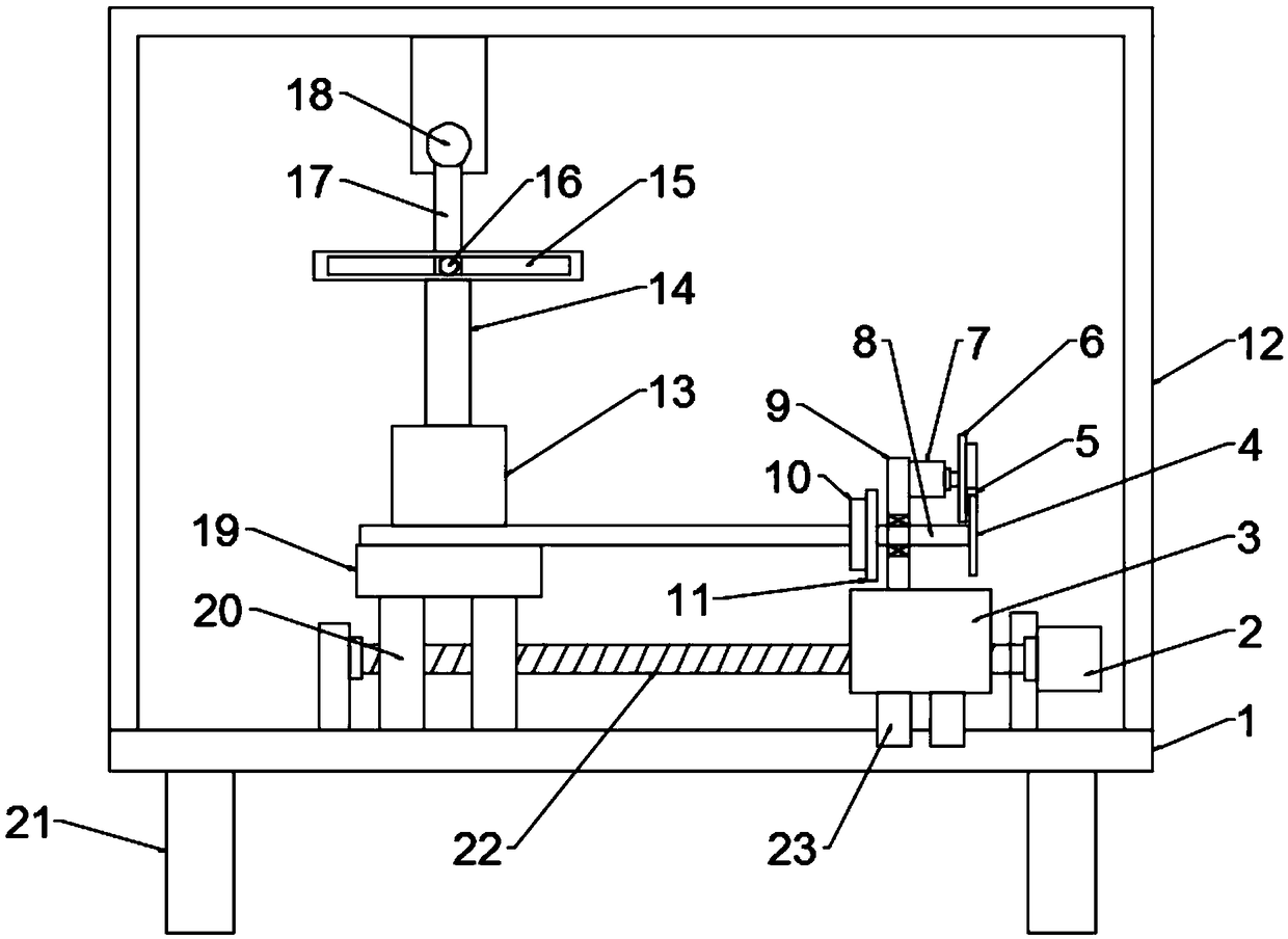
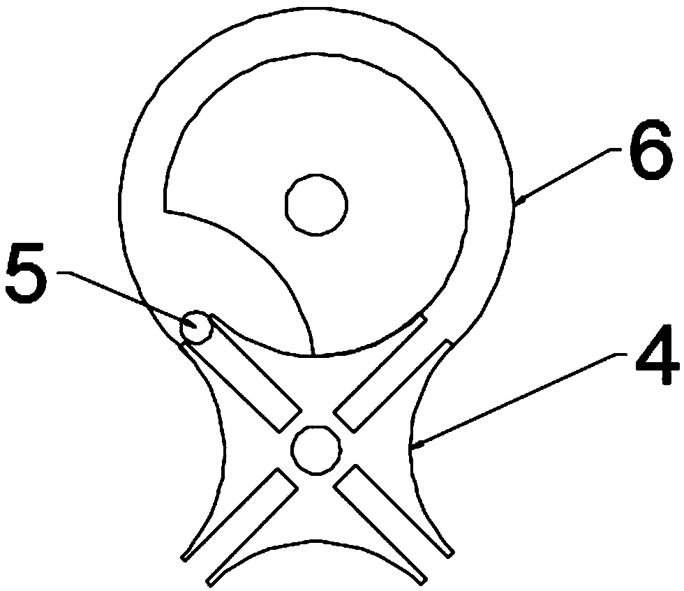
[0021] see Figure 1~2 , in an embodiment of the present invention, a forging equipment for hardware production, including a base plate 1, a workbench 19 and a forging hammer 13, support legs 21 are installed on the bottom four corners of the base plate 1, and a mounting frame is fixed on the base plate 1 12. A workbench 19 is installed on one side of the upper surface of the base plate 1 through a fixed rod 20, a forging hammer 13 is arranged above the workbench 19, a screw rod 22 is set between the base plate 1 and the workbench 19, and the screw rod 22 passes through the bearing and the mounting plate Rotate and install on the base plate, the right end of the screw rod 22 is fixedly connected with the output shaft of the first motor 2 through a coupling, the first motor 2 is mounted on the mounting plate by screws, and the screw rod 22 is provided with a movable seat 3 on the outside. Rod 22 is threadedly connected with movable seat 3, and both sides of movable seat 3 botto...

Embodiment 2

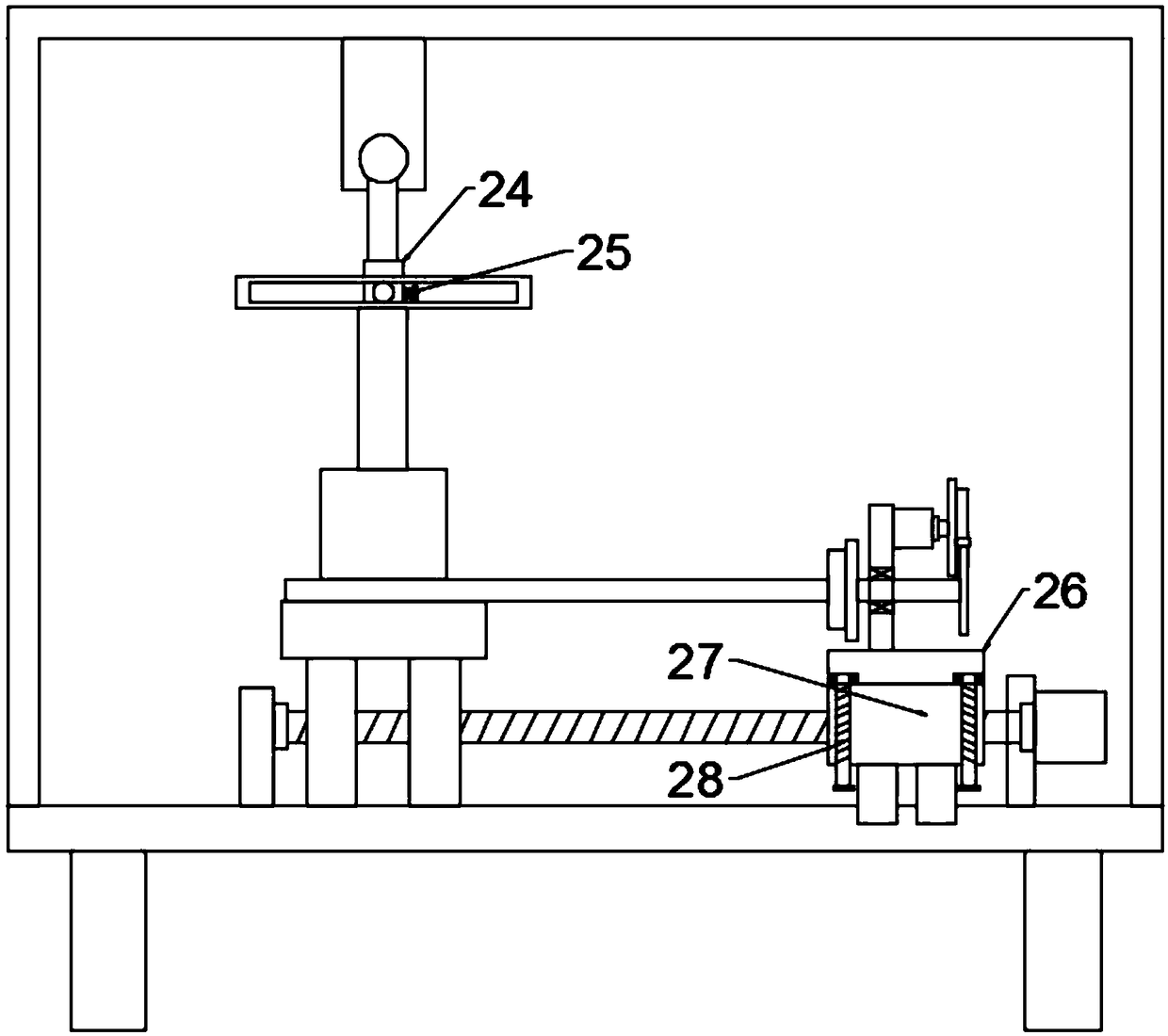
[0023] see image 3 The difference between this embodiment and Embodiment 1 is that a sleeve 24 is sleeved on the outside of the rotating rod 17, and the sleeve 24 is fixedly connected with the rotating rod 17 through a fastening bolt 25, and the second cylindrical pin 16 is fixed by welding On the sleeve 24, the movable seat 3 includes a first seat body 26 and a second seat body 27, the first seat body 26 is located directly above the second seat body 27, and the screw rod 22 passes through the second seat body 27 And threaded with it, the second base body 27 both sides are all pierced with threaded rod 28, the threaded rod 28 is threaded with the second base body 27, the top of the threaded rod 28 is rotatably connected with the first base body 26 through the bearing, by rotating Threaded rod 28, so as to be able to adjust the height of the first seat 26, so that when forging workpieces of different thicknesses, they can be highly matched with the workbench 19, and when forg...


PUM


Abstract

The invention discloses forging equipment for small hardware production, and relates to the technical field of small hardware production equipment. In order to solve the problem that to-be-forged workpieces are rotated manually, the forging equipment comprises a base board, a workbench and a forging hammer; a lead screw is arranged between the base and the workbench; the lead screw is sleeved witha movable base; the top of the movable base is fixedly provided with a supporting board in a welding mode; the supporting board is provided with a rotary shaft through a bearing; a grooved pulley mechanism is arranged on the right portion of the rotary shaft and comprises a second motor, a drive shifting plate and a driven grooved pulley; a third motor is installed at the position, over the workbench, of the top of a mounting frame; a rotary rod is welded and fixed to the end portion of an output shaft of the third motor; a T-type rod is connected with the front side of the rotary rod in a matched mode; and the forging hammer is welded and fixed to the bottom end of the T-type rod. Through arrangement of a first motor, the lead screw, the movable base, the grooved pulley mechanism, the third motor, the rotary rod and the T-type rod, the forging portion can be continuously adjusted, forging is made more sufficient, and the forging efficiency is improved.

Description

technical field [0001] The invention relates to the technical field of hardware production equipment, in particular to forging equipment for hardware production. Background technique [0002] Hardware refers to the general designation of metal parts and certain small tools installed on buildings or furniture, such as nails, screws, wires, locks, hinges, latches, springs, etc. Hardware refers to the five metal materials of gold, silver, copper, iron, and tin. Hardware is the mother of industry and the foundation of national defense. [0003] Forging is a processing method that uses forging machinery to apply pressure to metal blanks to cause plastic deformation to obtain forgings with certain mechanical properties, certain shapes and sizes. It is one of the two major components of forging (forging and stamping). Forging can eliminate defects such as as-cast porosity produced in the metal smelting process and optimize the microstructure. At the same time, due to the preservat...

Claims


Application Information

Patent Timeline
Patent Type & Authority Applications(China)
IPC IPC(8): B21J7/32B21J7/04
Inventor 黄连芝
Owner 黄连芝
Why Eureka
Try Eureka