
A sheet metal cutting machine that is convenient for adjusting the direction of workpieces

A technology for adjusting direction and sheet metal, applied in metal processing equipment, accessories of shearing machines, shearing devices, etc., can solve problems such as adjusting cutting direction, and achieve the effect of prolonging service life, reducing labor intensity, and convenient and quick operation.

Active Publication Date: 2019-12-03
上海松森特殊金属有限公司
View PDF7 Cites 0 Cited by
  • Summary
  • Abstract
  • Description
  • Claims
  • Application Information

AI Technical Summary

Problems solved by technology

[0003] In the production and processing of metal sheets, it is necessary to cut the sheets to obtain sheets of a specific size. The existing cutting methods are generally machine cutting, but there are defects in the existing cutting methods, and it is impossible to adjust the cutting direction conveniently. The person lifts the sheet metal and turns it, changing its orientation to achieve another cutting operation

Method used


Image

  • A sheet metal cutting machine that is convenient for adjusting the direction of workpieces
  • A sheet metal cutting machine that is convenient for adjusting the direction of workpieces
  • A sheet metal cutting machine that is convenient for adjusting the direction of workpieces

Examples


Embodiment 1

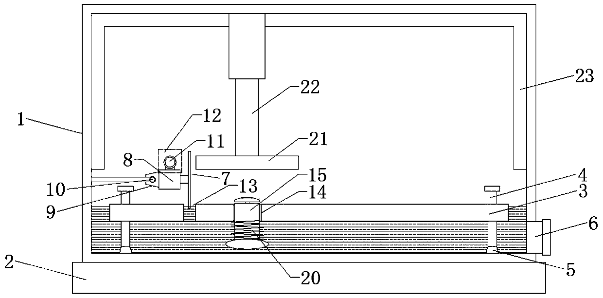
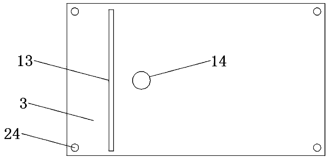
[0020] Please refer to the figure, in the embodiment of the present invention, a kind of sheet metal cutting machine that is convenient for adjusting the direction of the workpiece includes a box body 1, a base 2, a cutting table 3, a cutting knife 7 and a cutting motor 8; the box body 1 is fixed on the base 2, the cutting table 3 is horizontally located in the box body 1, and the four corners of the cutting table 3 are provided with threaded holes 24, and the internal threads of the threaded holes 24 are equipped with vertical support studs 4, and the support studs 4 can be adjusted as required, so that Change the height of cutting table 3, the lower end of supporting stud 4 fixes supporting foot 5, and the material of supporting foot 5 is rubber, plays the effect of supporting shock-absorbing noise reduction; Cutting knife 7 is vertically arranged on the top of cutting table 3, and cutting knife The central axis of 7 is fixedly connected on the output shaft of cutting motor 8...

Embodiment 2

[0027] A horizontal pressure plate 21 is arranged above the jacking mechanism, and the pressure plate 21 is fixed on the lower end of the hydraulic mechanism 22, and the hydraulic mechanism 22 is fixed on the top of the box body 1. The hydraulic mechanism 22 is mainly composed of a hydraulic cylinder, an oil pump, an oil tank, and a control switch. , the hydraulic mechanism 22 drives the pressing plate 21 to press down on the metal sheet below, press the metal sheet on the cutting table 3, and keep it fixed during cutting.


PUM


Abstract

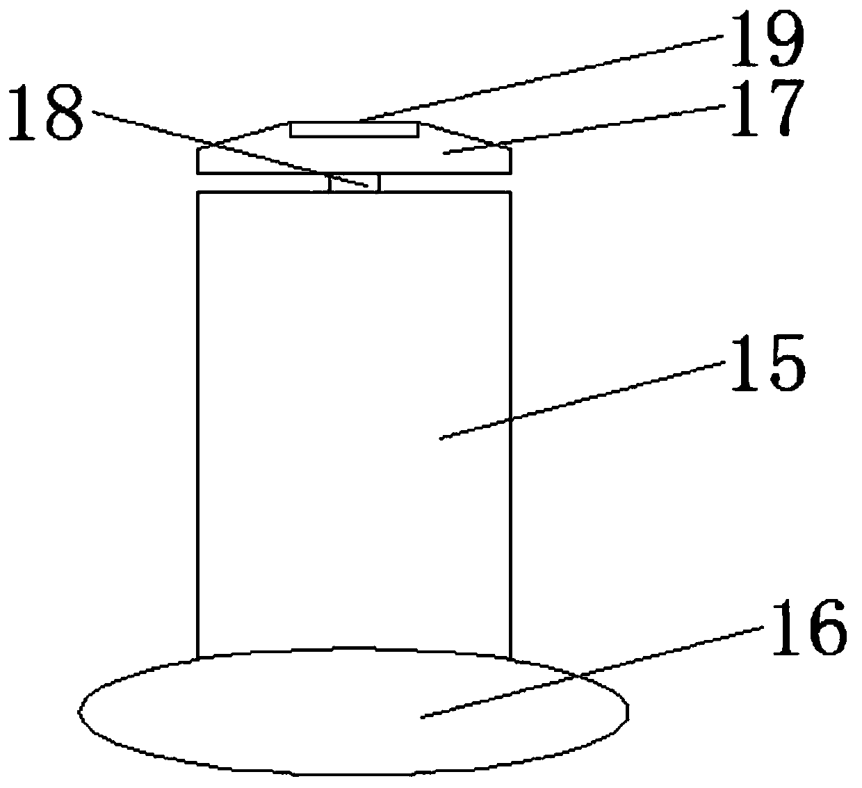
The invention relates to a machining machine, in particular to a metal panel cutting machine facilitating workpiece direction adjustment. A box body, a base, a cutting table, a cutting tool and a cutting motor are included. A center shaft of the cutting tool is fixedly connected to an output shaft of the cutting motor, a motor base is in threaded connection with a horizontal drive screw, and the other end of the drive screw is fixedly connected to an output shaft of a drive motor. The box body is filled with cooling water, the liquid level of the cooling water is higher than the lower end of the cutting tool so that the cutting tool can make contact with the cooling water, and the temperature of the cutting tool is reduced. The right side of a cutting tool groove is provided with a heightadjustable jacking mechanism, and the jacking mechanism is used for jacking a metal panel placed on the cutting table. The jacking mechanism can be used for jacking the metal panel under the situationthat no pressure exists on the metal panel, the metal panel rotates around the jacking mechanism, the part, towards the cutting tool, of the metal panel is changed, and different parts on the metal panel are cut.

Description

technical field [0001] The invention relates to the field of metal processing, in particular to a sheet metal cutting machine which is convenient for adjusting the direction of workpieces. Background technique [0002] Metal is a material with luster, ductility, and easy conduction and heat conduction. The above-mentioned properties of metals are related to the free electrons contained in metal crystals. In nature, most metals exist in a compound state. A few metals such as Gold, platinum, silver and bismuth exist in a free state. Metal minerals are mostly oxides and sulfides. Other forms of existence are chlorides, sulfates, carbonates and silicates. The connection between metals is a metal bond, so it is optional The connection can be re-established even if the position is changed, which is why the metal has good ductility. [0003] In the production and processing of metal sheets, it is necessary to cut the sheets to obtain sheets of a specific size. The existing cutting...

Claims


Application Information

Patent Timeline
Patent Type & Authority Patents(China)
IPC IPC(8): B23D15/06B23D33/02B23D19/00
CPCB23D15/06B23D19/00B23D33/02
Inventor 王飞
Owner 上海松森特殊金属有限公司
Learn More