Full-automatic magnetic ring chamfering grinding equipment for continuously conveying magnetic rings

A fully automatic, magnetic ring technology, applied in the field of fully automatic magnetic ring chamfering and grinding equipment, can solve the problems of alignment deviation, high labor intensity, and affecting the quality of magnetic ring chamfering and grinding, so as to reduce production costs and improve production Efficiency, strong effect of processing continuity

Active Publication Date: 2019-03-01
WENZHOU POLYTECHNIC
View PDF16 Cites 3 Cited by
  • Summary
  • Abstract
  • Description
  • Claims
  • Application Information

AI Technical Summary

Problems solved by technology

The processing of the burr of the outer circle is the same as the above method. The worker needs to place the grinding wheel on the outer ring of the magnetic ring to repeat the operation. This manual chamfering method requires the worker to operate the whole process, which is not only slow and inefficient, but also labor-intensive and safe. The main disadvantage is that the quality and consistency of the product are difficult to guarantee
[0004] In addition, it is easy to load the magnetic rings one by one, and workers can easily stack two magnetic rings as one magnetic ring for feeding, which will easily affect the subsequent chamfering and grinding process; and the magnetic rings are easy to shift during feeding, resulting in subsequent Alignment deviation is caused during chamfering and grinding, which affects the chamfering quality of the magnetic ring

Method used


Image

  • Full-automatic magnetic ring chamfering grinding equipment for continuously conveying magnetic rings
  • Full-automatic magnetic ring chamfering grinding equipment for continuously conveying magnetic rings
  • Full-automatic magnetic ring chamfering grinding equipment for continuously conveying magnetic rings

Examples


Embodiment Construction

[0030] The present invention will be described in further detail below in conjunction with the accompanying drawings.

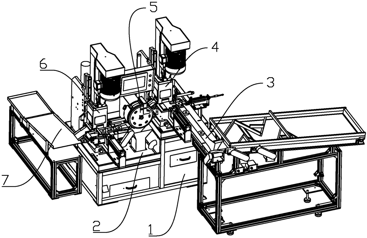
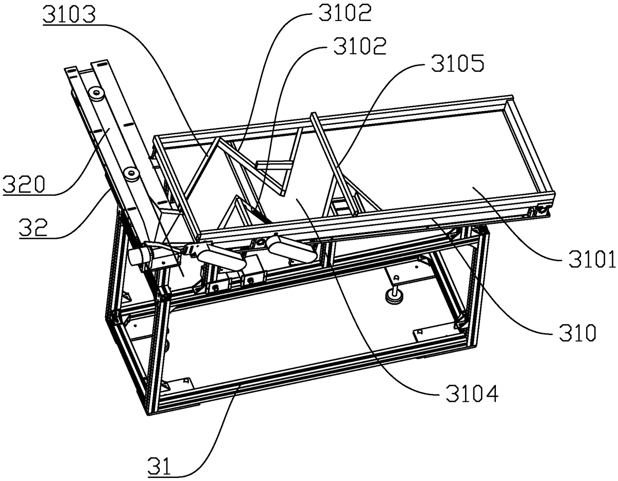
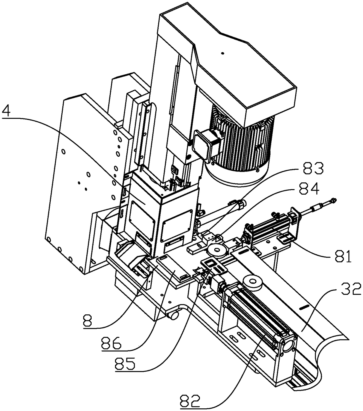
[0031] refer to figure 1 , a fully automatic magnetic ring chamfering and grinding equipment for continuously conveying magnetic rings, comprising a machine base 1, a feeding mechanism 3, a first grinding mechanism 4, a turning mechanism 5, a second grinding mechanism 6 and a feeding mechanism 7. Wherein, machine base 1 is as bearing structure, comprises a working platform 2, and this working platform 2 has material feeding end and unloading end; The magnetic ring; the first grinding mechanism 4, which is located on the top of the working platform 2 and is fixedly connected with the feeding mechanism 3, is used to continuously receive the magnetic ring delivered by the feeding mechanism 3, and the inner ring of one end surface of the magnetic ring and the outer ring are polished at the same time; the turning mechanism 5, which is located on the top of the wo...


PUM


Abstract

The invention discloses full-automatic magnetic ring chamfering grinding equipment for continuously conveying the magnetic rings. The full-automatic magnetic ring chamfering grinding equipment comprises a base, a feeding mechanism, a first grinding mechanism, an overturning mechanism, a second grinding mechanism and a discharging mechanism, wherein the first grinding mechanism and the second grinding mechanism both comprise a chamfering head assembly and a pushing-out assembly, the chamfering head assembly comprises a main shaft motor, a main shaft support, a power head and a chamfering disc,the main shaft motor is connected with the chamfering disc through the power head, the chamfering disc is provided with two chamfering tool mounting blocks, through holes are formed in the two chamfering tool mounting blocks, a transverse hole is formed in the chamfering disc, the two chamfering tool mounting blocks are connected the positions of the inner ring and the outer ring of the magnetic ring correspond to each other respectively and are fixed by screws; a limiting block is arranged below the chamfering head assembly, the height of the cross section of the limiting block is lower thanthat of the magnetic ring; and the pushing-out assembly comprises a pushing-out air cylinder and a pushing-out block. The full-automatic magnetic ring chamfering grinding equipment has the following advantages and effects that the inner ring and the outer ring of the two end surfaces of the magnetic ring can be subjected to chamfering and grinding, labor is saved, and production efficiency is improved.

Description

technical field [0001] The invention relates to the technical field of magnetic ring processing equipment, in particular to a fully automatic magnetic ring chamfering and grinding equipment for continuously conveying magnetic rings. Background technique [0002] Magnetic rings are widely used in transformers, sensors, and power communication equipment. In order to prevent the coating quality from being affected by the burrs of the magnetic ring during the coating process of the magnetic ring, and to make the magnetic ring more tightly wound around the coil, the magnetic ring needs to be chamfered and polished. [0003] Usually, after the magnetic ring is pressed by the molding machine, there will be burrs on the inner and outer circles of the two end faces. The burrs on the inner circle have always been removed by manual chamfering. The method of manual chamfering is to install a motor on the workbench. , and then install a conical grinding wheel on the motor, the worker pl...

Claims


Application Information

Patent Timeline
Patent Type & Authority Applications(China)
IPC IPC(8): B23D79/00
CPCB23D79/00
Inventor 谷志阳
Owner WENZHOU POLYTECHNIC
Why Eureka
Try Eureka