Rotor support shaft-pressing tool

A technology for rotor brackets and finalizers, which is applied in electromechanical devices, manufacturing tools, metal processing, etc., can solve problems such as difficulty in continuous batch manufacturing, high surface temperature of workpieces, and poor production site environment, so as to reduce single-person operations The effect of cost reduction, labor intensity reduction, and production cost reduction

Pending Publication Date: 2019-03-01
迈思维动力技术(常州)有限公司
View PDF0 Cites 2 Cited by
  • Summary
  • Abstract
  • Description
  • Claims
  • Application Information

AI Technical Summary

Problems solved by technology

However, there are many defects in this method, such as heating the workpiece, which needs to consume more electric energy; the surface temperature of the workpiece is too high, which is prone to burn accidents; when the metal parts are supplied, there will be a small amount of anti-rust oil on the surface, which will generate smoke after heating. and pungent smell, so that the production site environment is very poor, affecting customer visits; there are heating and cooling links in the workpiece, which makes it difficult to achieve continuous mass production; the heat-fitting process requires a high level of experience for the operator. Manual operation, If there is a slight error, the workpiece is easily scrapped

Method used


Image

  • Rotor support shaft-pressing tool
  • Rotor support shaft-pressing tool
  • Rotor support shaft-pressing tool

Examples


Embodiment 1

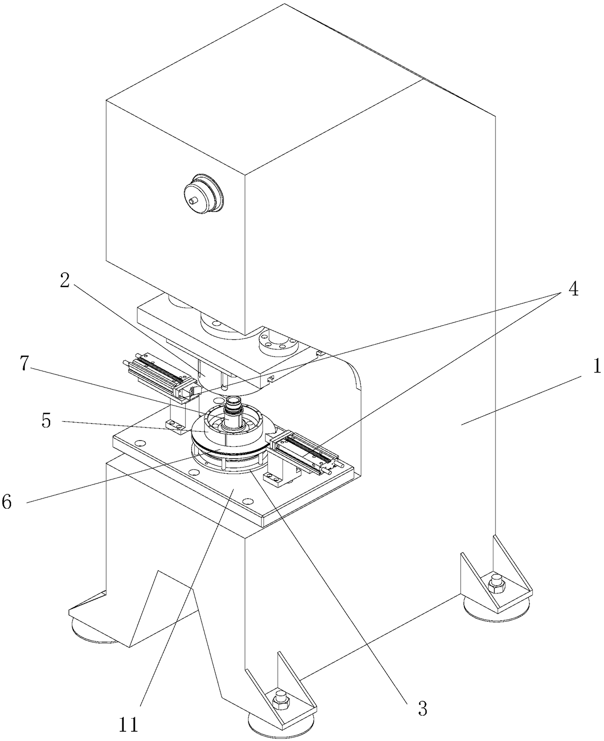
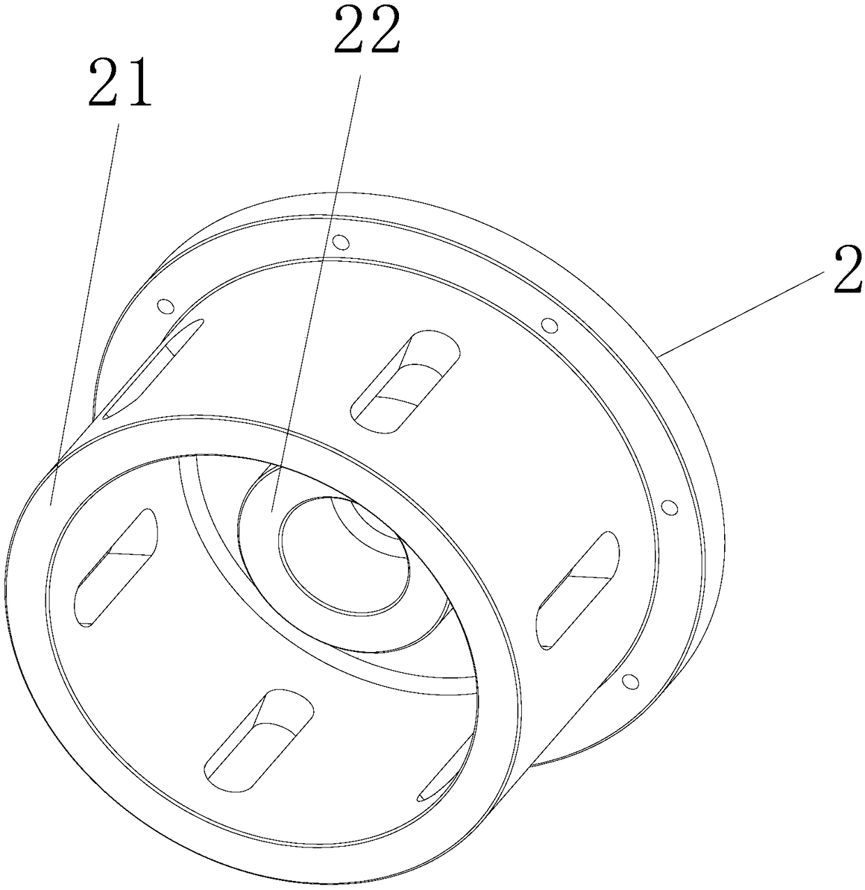
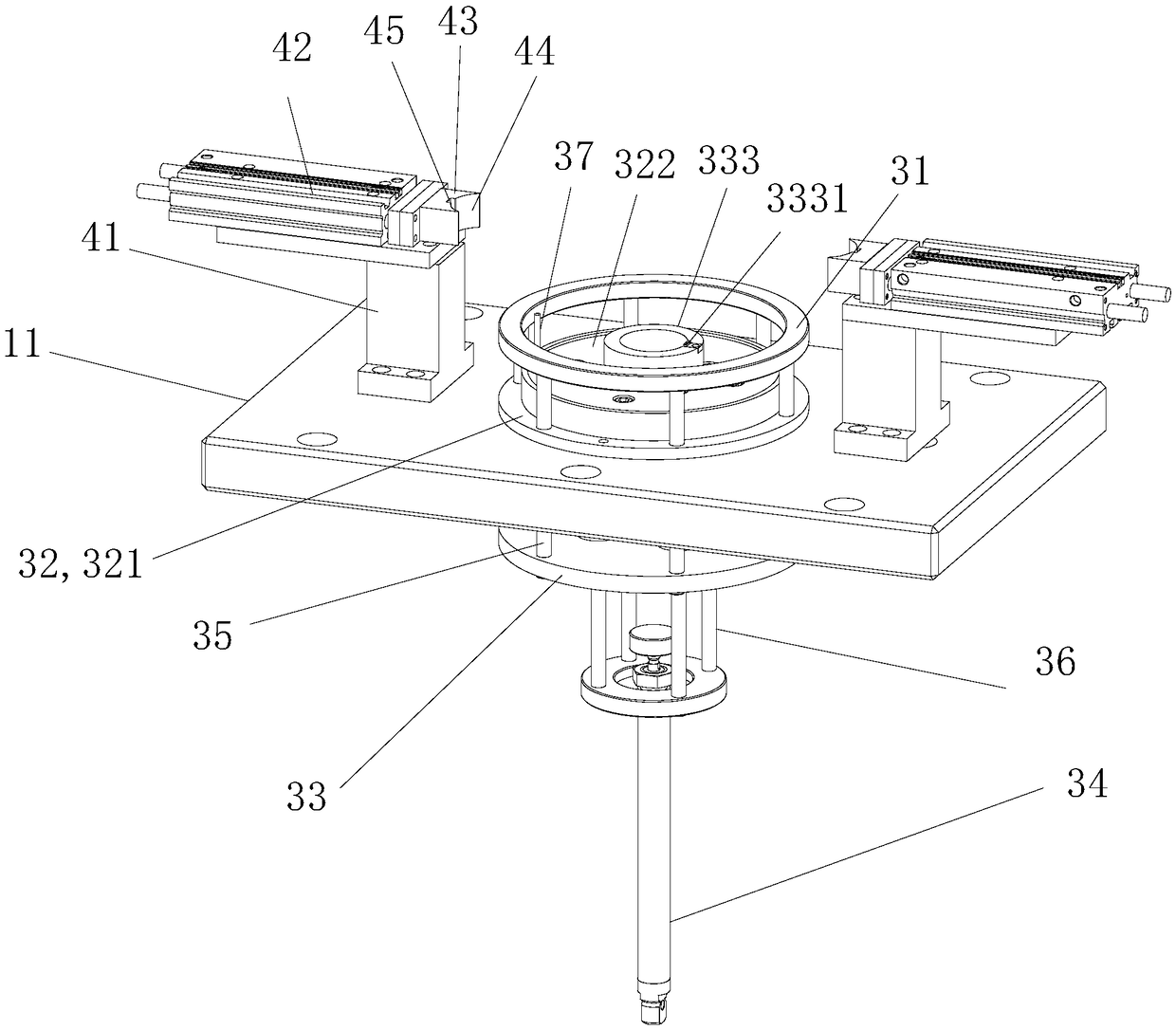
[0032] See Figure 1 to Figure 4 , the rotor bracket finale tooling of this embodiment includes a press 1 , a pressure head 2 , a balance end plate positioning mechanism 3 and a rotating shaft positioning mechanism 4 .

[0033] The press 1 is provided with a support platform 11, and the support platform 11 is fixed on the press by bolts and can be disassembled and assembled independently. The balanced end plate positioning mechanism 3 is installed on the supporting platform 11 , and the balanced end plate positioning mechanism 3 is used to carry the rotor bracket 5 and the balanced end plate 6 sheathed on the rotor bracket 5 . The balance end plate positioning mechanism 3 includes a support plate 31, a positioning plate 32, a bottom plate 33 and a driver 34. In this embodiment, the support plate 31 is an annular component, and the driver 34 is an oil cylinder. The balance end plate 6 is placed on the support plate 31 , and the rotor bracket 5 is placed on the positioning plat...


PUM


Abstract

The invention discloses a rotor support shaft-pressing tool. The rotor support shaft-pressing tool comprises a press machine, a pressing head and a balance end plate positioning mechanism; the press machine is provided with a supporting platform, the balance end plate positioning mechanism is arranged on the supporting platform, the balance end plate positioning mechanism is used for bearing a rotor support and a balance end plate arranged on the rotor support in a sleeved mode, the pressing head is located right above the balance end plate positioning mechanism and is connected with the pressmachine, the bottom surface of the pressing head is provided with an outer extrusion surface used for extruding the balance end plate, the outer extrusion surface acts on the balance end plate, so that the balance end plate is fixedly connected with the rotor support. The tool has the characteristics of being low in energy consumption, safe to operate, clean in field environment, reliable in quality, high in production efficiency and the like.

Description

technical field [0001] The invention belongs to the technical field of production of automobile motor rotors, and in particular relates to a tooling for finalizing a shaft of a rotor support. Background technique [0002] The rotor of the motor includes components such as a rotating shaft, an iron core, an end plate, and a commutator. The current assembly process is as follows: first heat the rotor bracket to 200 degrees Celsius in an oven, manually insert the rotating shaft into the middle hole of the rotor bracket, and position it with a key; then heat the balance end plate in the oven to at least 100 degrees Celsius, and manually insert the Put it into the rotor bracket (cooled to below 45 degrees Celsius), and adjust the position to ensure that the pin hole is concentric; finally, knock the pin into the pin hole with a copper rod to fix the position of the rotor bracket and the phase plate of the balance end plate. However, there are many defects in this method, such as...

Claims


Application Information

Patent Timeline
Patent Type & Authority Applications(China)
IPC IPC(8): B23P19/02H02K15/00
CPCB23P19/02B23P2700/50H02K15/00
Inventor 李森亚王兴保刘宏
Owner 迈思维动力技术(常州)有限公司
Why Eureka
Try Eureka