Tubular metal bar rust removal device
A metal rod and cylindrical technology, which is applied in the field of cylindrical metal rod derusting devices, can solve the problems of low efficiency and inconvenient operation, and achieve the effect of improving derusting efficiency, simple and compact structure, and easy to carry and operate
- Summary
- Abstract
- Description
- Claims
- Application Information
AI Technical Summary
Problems solved by technology
Method used
Image

Examples
Embodiment 1
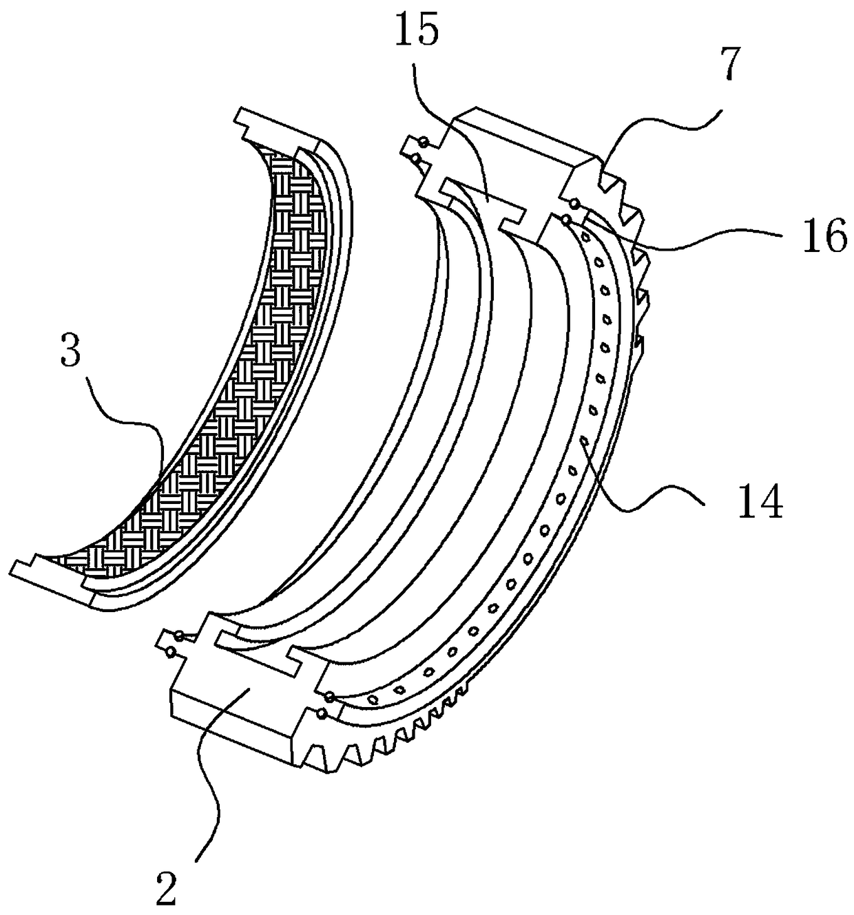
[0024] A cylindrical metal rod derusting device according to the embodiment includes a pipe body 1, and a brush ring 2 coaxial with the pipe body 1 and rotatable in the pipe body 1 is arranged in the pipe body 1, and the pipe body 1 is set on the Sliding back and forth on the metal rod and derusting by the metal brush 3 arranged on the brush ring 2. This device is a tubular structure, which can be directly placed on the metal rod from one end of the metal rod, and then the user slides the tube body 1 back and forth on the metal rod and uses the metal brush 3 provided inside to remove the rust on the surface of the metal rod. Remove, so as to achieve the effect of rust removal. Because the brush ring 2 is an annular structure, it can rotate in the tube body 1 . Because the metal brush 3 is provided with a metal wire with a higher density, and when the tube body 1 is placed on the outer wall of the metal tube, the length of the metal wire is greater than the distance between th...
Embodiment 2
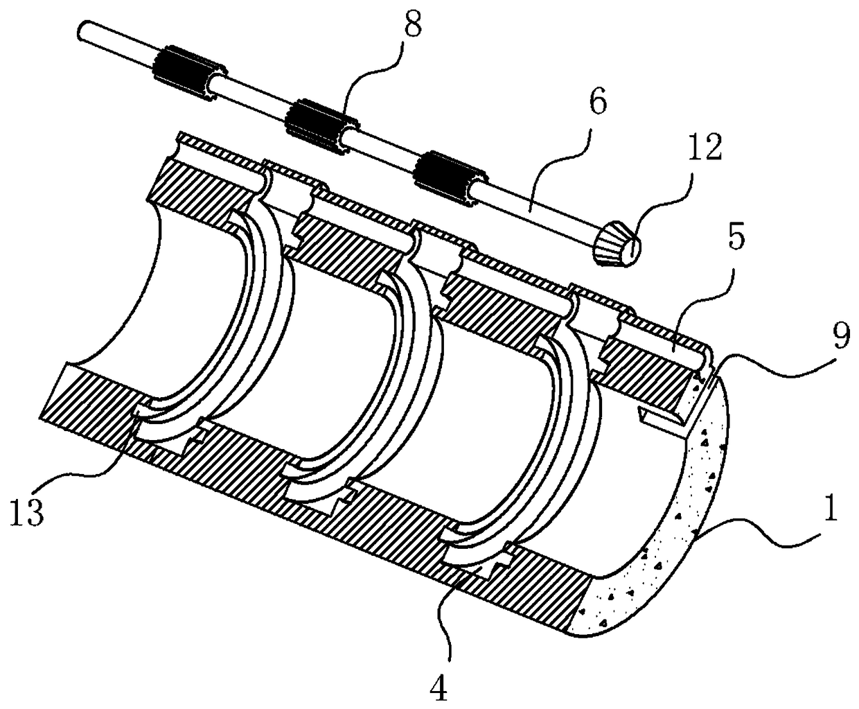
[0026] This embodiment is further defined on the basis of the above embodiments, as figure 1 As shown, at least two annular grooves 4 perpendicular to the axis are equidistantly arranged on the inner wall of the pipe body 1 along the axial direction, and the brush ring 2 is embedded in the annular grooves 4 and slides in the annular grooves 4 . Anti-slip lines are provided on the outer wall of the pipe body 1 . Here, the connection method between the brush ring 2 and the pipe body 1 is limited, and the structure of the annular groove 4 cooperates with the brush ring 2 to achieve the effect of fixing and limiting, and at the same time, it can ensure that the brush ring 2 can rotate stably. Other parts of this embodiment are the same as those of the foregoing embodiment, and will not be repeated here.
Embodiment 3
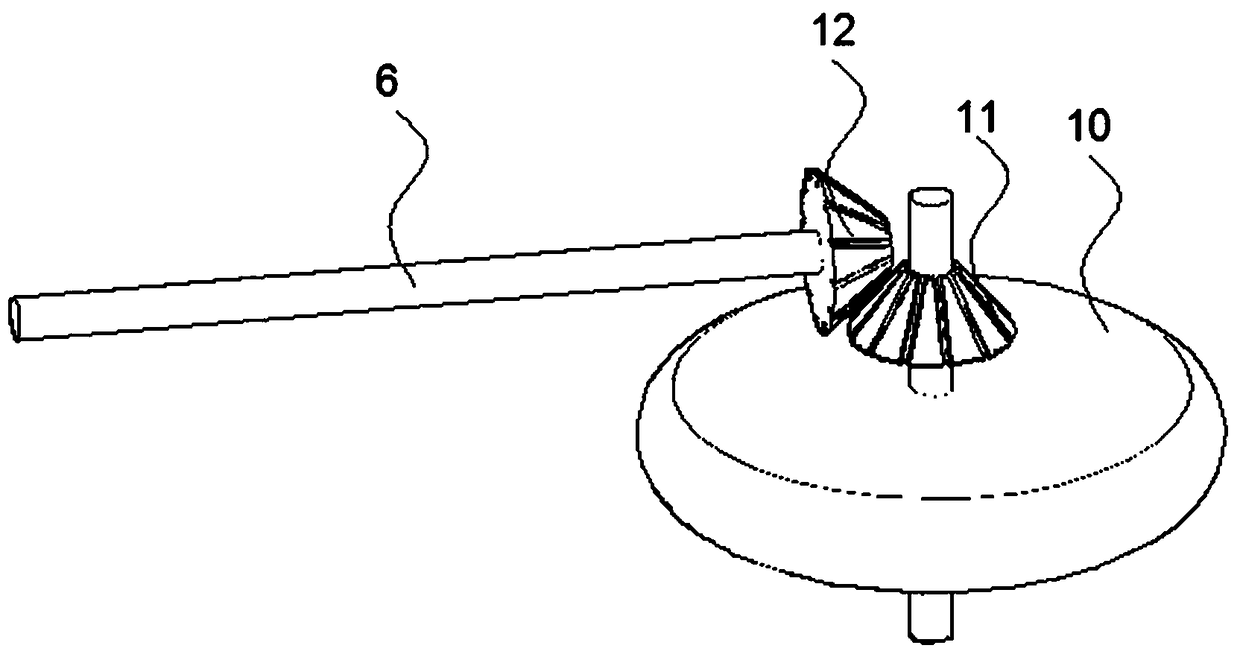
[0028] This embodiment is further defined on the basis of the above embodiments, as figure 1 , figure 2 and image 3 shown, where figure 1 Only the internal structure of the pipe body 1 is fully presented, and the specific setting position and size of the roller 10 and the specific setting position of the bevel gear are not marked out, because its specific connection method and structure are beyond the knowledge of those skilled in the art. Known technical means, those skilled in the art according to figure 1 and figure 2 The schematic diagram of the structure can understand its principle and connection mode, so it is not marked in detail in the attached drawings. A shaft tube 5 parallel to the axis of the tube body 1 is provided on the outer wall of the tube body 1. The shaft tube 5 communicates with each annular groove 4 and a rotating shaft 6 is provided in the shaft tube 5, while a shaft tube 5 is provided on the outer wall of the brush ring 2. There is a toothed be...
PUM
 Abstract
Description
Claims
Application Information
 - R&D Engineer
- R&D Manager
- IP Professional
- Industry Leading Data Capabilities
- Powerful AI technology
- Patent DNA Extraction
Browse by: Latest US Patents, China's latest patents, Technical Efficacy Thesaurus, Application Domain, Technology Topic.
© 2024 PatSnap. All rights reserved.Legal|Privacy policy|Modern Slavery Act Transparency Statement|Sitemap